Note
The HD-1420 connects between your antenna and your receiver and permits reception of VLF signals between 10 and 500 kHz. These signals are fed from the converter to your receiver and appear between 3510 and 4000 kHz. The actual frequency of the VLF station being received is the dial frequency shown on your receiver minus 3500 kHz. For example: 280 kHz reads 3780 kHz (3780–3500=280).
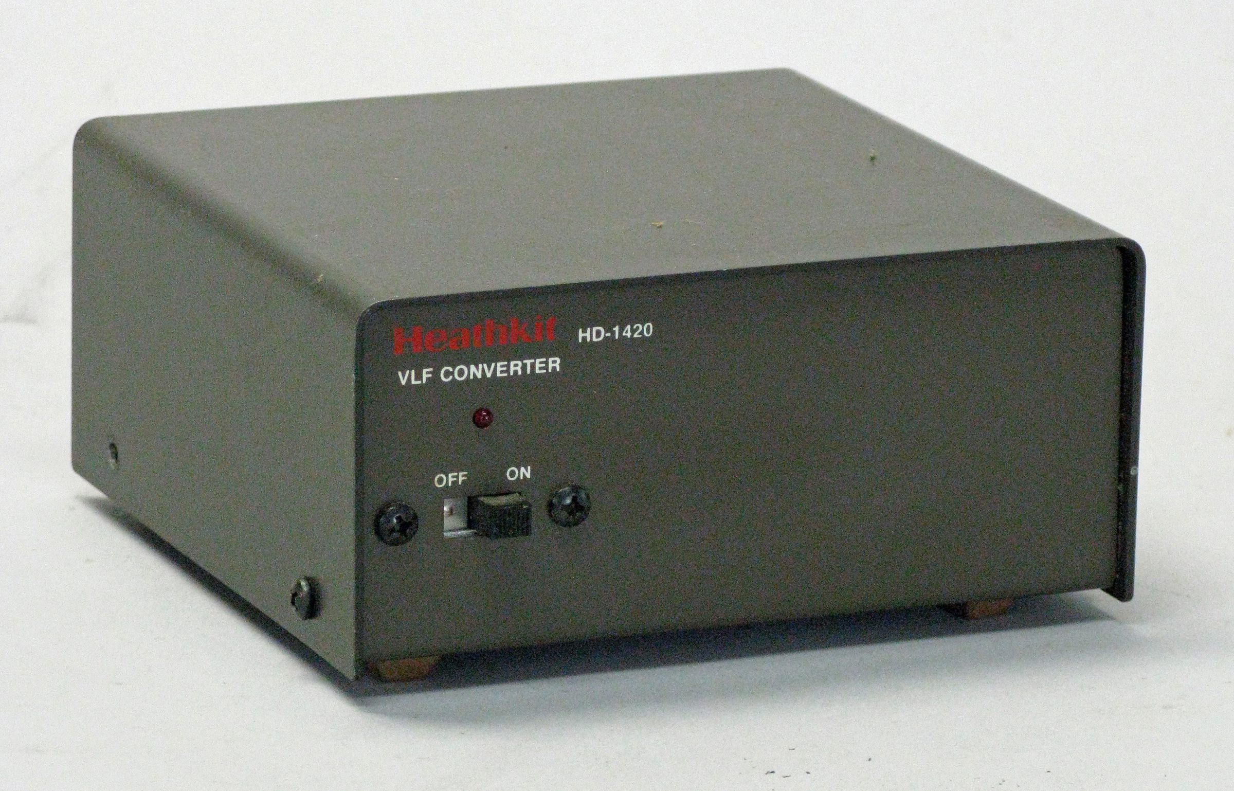
The HD-1420 is about as simple a device as one could ask for. There is no alignment or tuning to be done. The front panel contains only a pilot light and a single control—the on/off switch. Just connect the box and turn it on.
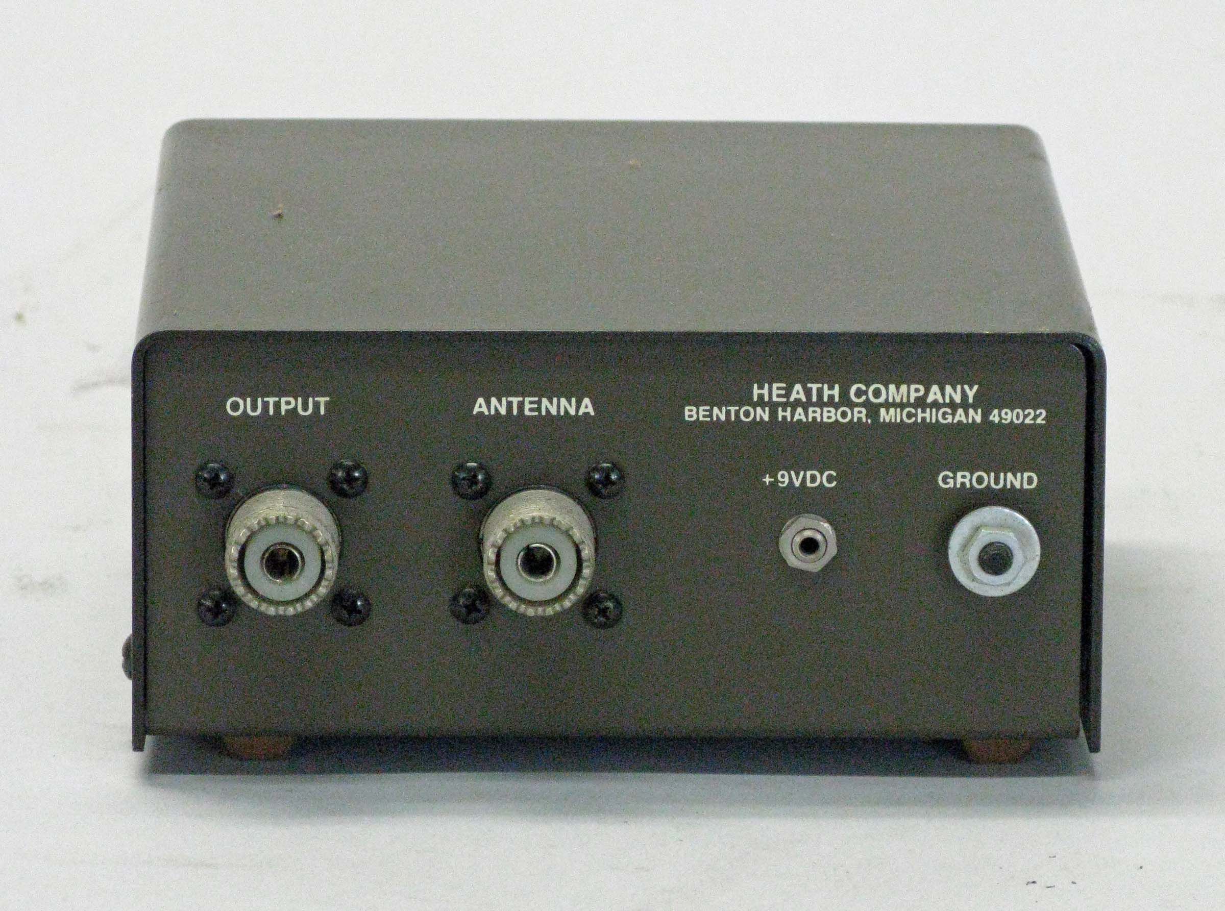
Rear panel connections include only the power connector and two SO-239s (input from antenna and output to receiver). When unit is switched off, signals are bypassed around it.
A few tips on use:
* Be sure to use a shielded cable between the converter and your receiver. This will cut down on interference from 80 meters.
* A good antenna is essential—and a vertical one is best, followed by a long random wire.
* Any long wire antenna will do—the longer the better.
Warning: If you use the HD-1420 with a transceiver of any kind be sure to remove the converter from the RF line before transmitting. Failure to do so will result in destruction of the converter.
The HD-1420 uses one IC and two transistors and runs on one 9 volt transistor battery, or 6 to 14 VDC at 20 mA, and is enclosed in a brown cabinet.
References:
Review. QST. Nov 1986, p. 40.
Input frequencies: 10 kHz to 500 kHz
Output frequencies: 3510 to 4000 kHz
Sensitivity: 1.0 to 5.0 µV typical
Power requirements: 6 to 14 VDC, NEDA type 1604 9-volt battery (or external power adapter), 20 mA typical
Photos, general information and specifications from "Heathkit: A Guide to the Amateur Radio Products," by Chuck Penson, WA7ZZE. Used with permission.