Note
Heath released three “Single-Bander” transceivers (80, 40, and 20 meter models) in the summer of 1963. They became known popularly as “single banders” and were instantly successful.
These three units are identical in every way except for frequency coverage. The HW-12 covers 3.8 to 4.0 MHz—lower sideband only. The following is a general discussion of all three versions.
The Single-Banders are 14 tube SSB-only rigs covering the phone portions of their respective bands. The 80 and 40 meter versions operate only LSB while the 20 meter version operates only USB. Their power input is about 200 watts PEP from a pair of 6GE5s. All units are a superheterodyne design using crystal filter SSB generation. The units are built on a single large PC board and feature ALC, built-in PTT and VOX, fixed (slow) AVC action, and an illuminated S-meter and dial.
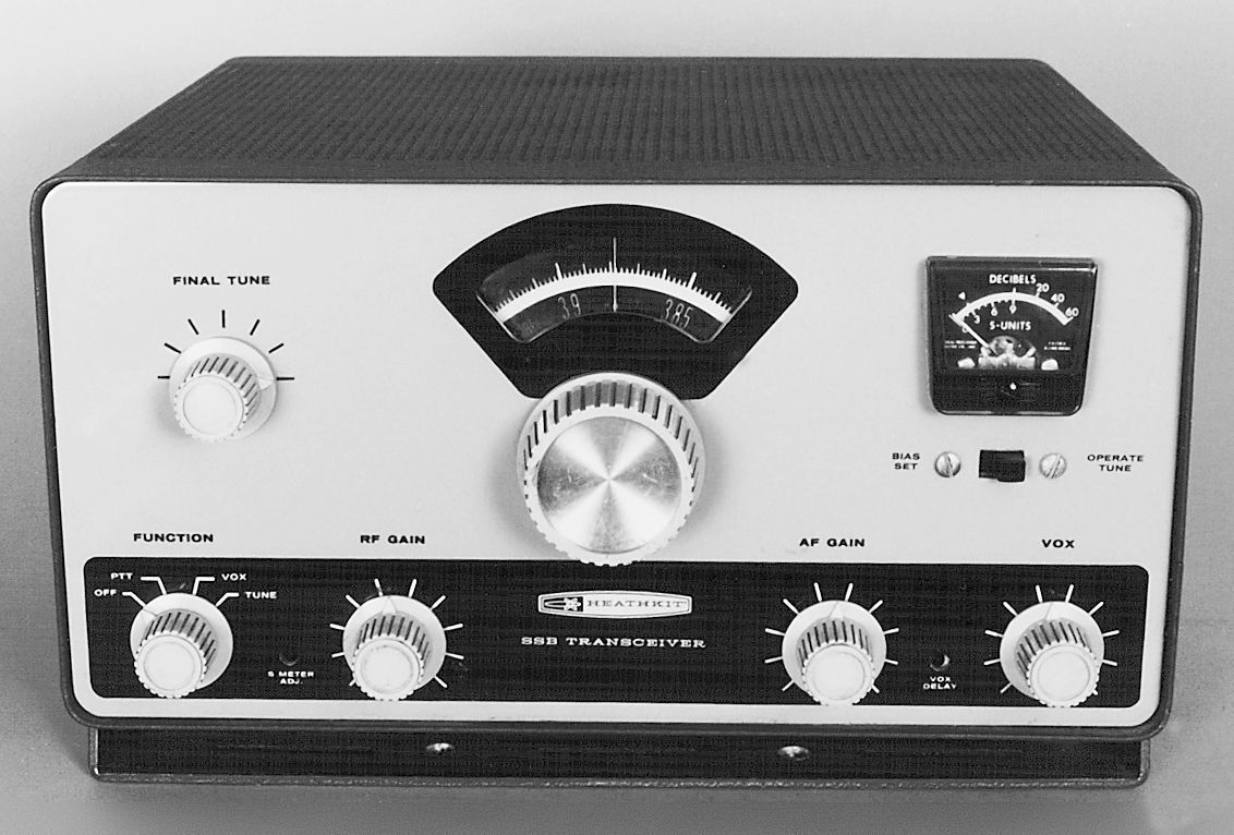
Front panel controls include main tuning, final tune, function (ON-OFF-PTT-VOX-TUNE), RF gain, AF gain (pull to turn on crystal calibrator), VOX gain, VOX delay, and S-meter zero adjust.
Rear panel controls include mike gain, tune level, and final bias adjust. Rear panel connections include Hi-Z mike connector, RCA jacks for 8Ω speaker (there is no built-in speaker), 50Ω antenna, external relay, separate receiver antenna input, and an octal plug for power input (for use with the HP-13 and HP-23 series power supplies). A carrier null control is located on the circuit board in the left rear corner.
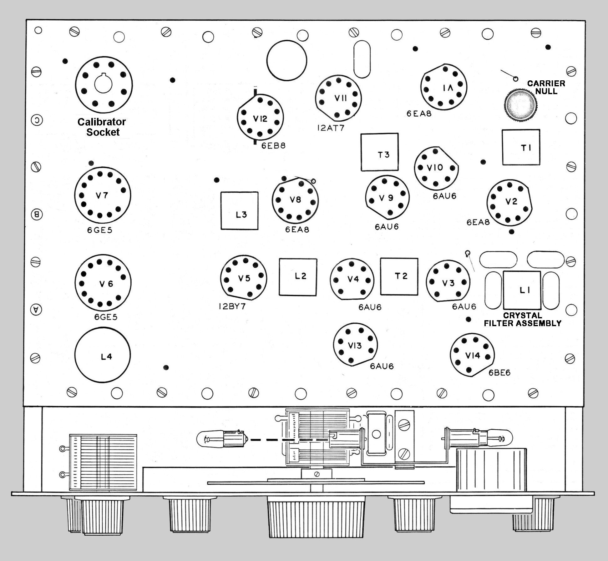
There is a socket for the optional HRA-10-1 crystal calibrator (the same one used in the HR-10). The presence of the calibrator can be determined with visual inspection by looking through the cabinet top. Look for it in the left rear corner of the rig. The calib
The single banders do not use the same modular crystal filters as found in the SB series. Instead, filters are made from discrete parts—a coil (L1) and four individuals crystals. The assembly is located on the right side of the circuit board, adjacent to V3. Refer to Figure 1.
Many units will be found with SO-239s added to replace the RCA antenna connector. The external relay jack provides a contact closure for use with amplifiers and for T/R relays for amplifiers without internal switching. Caution: One side of the external relay jack is connected to chassis ground and therefore should NOT be connected to AC lines. If you intend to use AC lines, do so through an isolation transformer. Also, if you are using low voltage DC switching, be sure to get the polarity right. The grounded DC lead must be connected to the outside (chassis side) of the jack.
In 1966, at least a couple of companies offered three-band modification kits for the single bander series. One of these companies was Dynalabs, whose ad for the upgrade kit can be seen in the January 1966 issue of QST magazine. rator is turned on by pulling out on the AF gain control.
The Single-Banders are enclosed in a cabinet painted in two-tone gloss finish green and use light gray DX-60 style plastic knobs. All three units were revamped in 1966 and re-released with an “A” on the model number. Single-Banders are not rare although it is difficult to find them in really good, unmodified condition. Many appear to have been well used. Beware all manner of strange modifications.
A Turner 350C hand microphone was optional. Refer to GH-12 for more information.
The Single-Banders are designed specifically for use with the HP-23 and HP-13 power supplies. HP-10 and HP-20 power supplies require some small modifications for use with these rigs. See Single-Bander assembly manual for complete details.
POWER PLUG CONNECTIONS
Pin 1: bias (–130 volts)
Pin 2: Ground
Pin 3: LV B+ (250 volts)*
Pin 4: HV B+ (800 volts)
Pin 5: switch
Pin 6: filament (12 VAC)
Pin 7: filament common
Pin 8: switch
*Caution: Run only at 250 VDC B+.
References:
Review. QST. Jan 1964, p. 48.
Modifications. QST. Apr 1965, p. 71.
Modifications (more on). QST. May 1965, p. 59.
Adding bands (reference only). CQ. Jan 1966 , p. 70.
Power supply for. CQ. Mar 1966, p. 48.
Alignment tip. QST. May 1966, p. 74.
Add switch for choice of 250/300 VDC. QST. May 1966, p. 75.
Fixing a rattle. QST. Dec 1966, p. 49.
Low voltage equalization. QST. Dec 1966, p. 49.
CW modification. CQ. Feb 1967, p. 36.
Dial modification. QST. Jun 1968, p. 36.
Carrier null adjustment. QST. Sep 1968, p. 51.
New gain control. QST. May 1969, p. 53.
160 meter operation. 73 Amateur Radio. Jun 1969, p. 12.
Noise limiter. Ham Radio. Mar 1971, p. 67.
CW coverage with. CQ. Jul 1971, p. 18.
Use on MARS. Ham Radio. Sep 1971, p. 63.
A receiver pre-amp for. CQ. Mar 1976, p. 26.
VFO slippage and backlash. QST. Sep 1976, 39.
Use as QRP. QST. Sep 1977, p. 45.
Receiver Section
Frequency coverage: 3.8 to 4.0 MHz
Receiver mode: lower sideband only
Sensitivity: 1.0 µV input will provide at least 15 db signal plus noise to noise ratio
Selectivity: 2.7 kHz @ 6 db, 6 kHz @ 50 db
IF: 2305 kHz
Image rejection: 100 db
IF rejection: 50 db
Receiver audio response: 400 to 3000 Hz
Receiver audio power output: 1 watt
External speaker impedance: 8Ω
Antenna input impedance: 50Ω nominal, unbalanced
Transmitter section
Frequency coverage: 3.8 to 4.0 MHz
Stability: less than 200 Hz per hour after one hour warmup
RF power output: 200 watts PEP
Unwanted sideband suppression: 45 db minimum below peak output @ 1000 Hz
Carrier suppression: 45 db minimum below peak output
Output impedance: 50Ω nominal, unbalanced
Transmitter audio response: 400 to 3100 Hz
Microphone required: hi-Z crystal, ceramic or dynamic; 10 mV minimum output
Power requirements:
800 VDC at 250 mA
250 VDC at 100 mA
–125 VDC at 5 mA
12 volts AC or DC at 3.75 amps
Tubes: (3) 6EA8, (5) 6AU6, (1) 6BE6, (1) 12AT7, (1) 12BY7, (1) 6EB8,
(2), 6GE5
Photos, general information and specifications from "Heathkit: A Guide to the Amateur Radio Products," by Chuck Penson, WA7ZZE. Used with permission.