Note
QST, May 1965, p. 143.
QST, Jan 1966, p. 129.
QST, Jul 1971, p. 114.
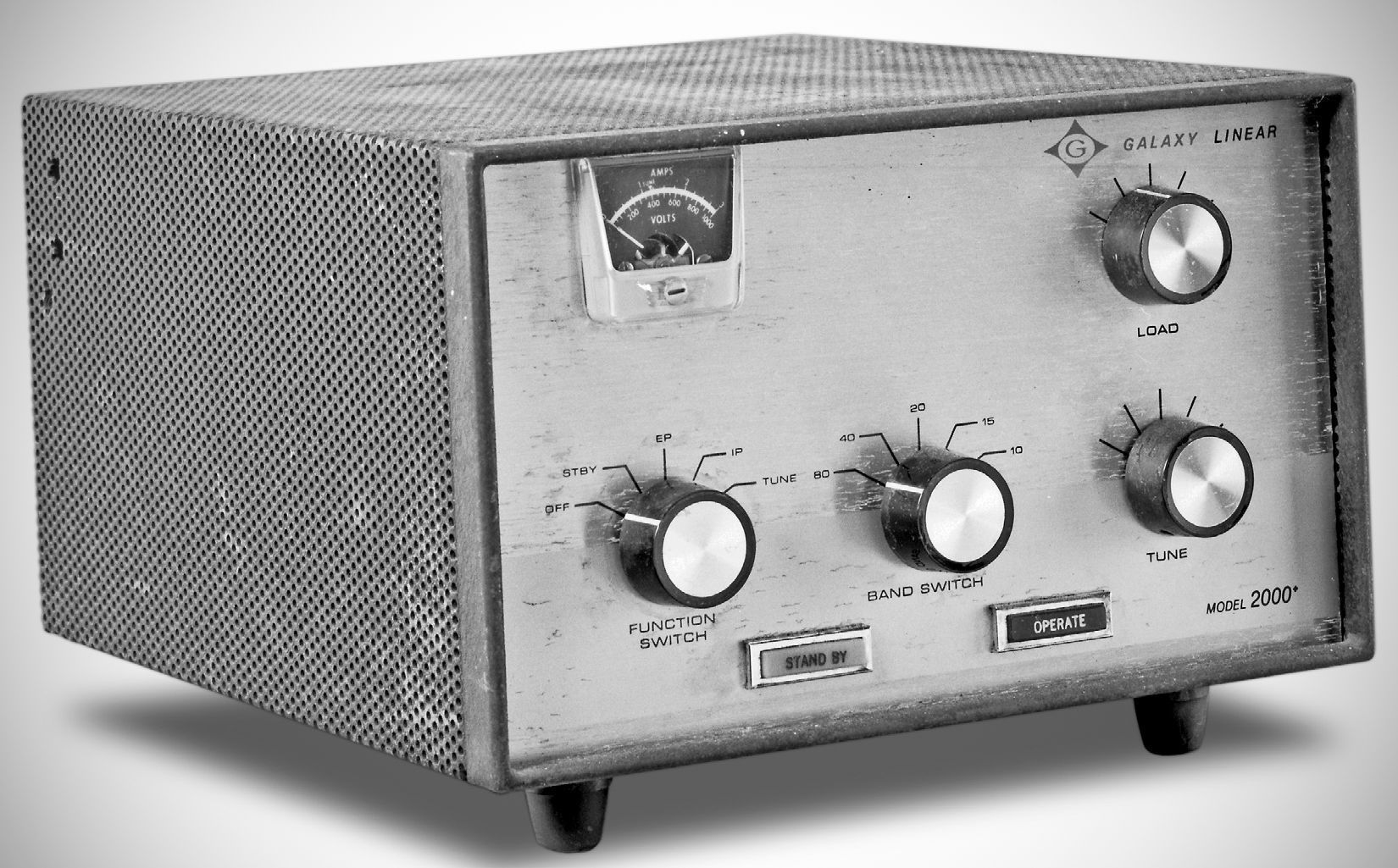
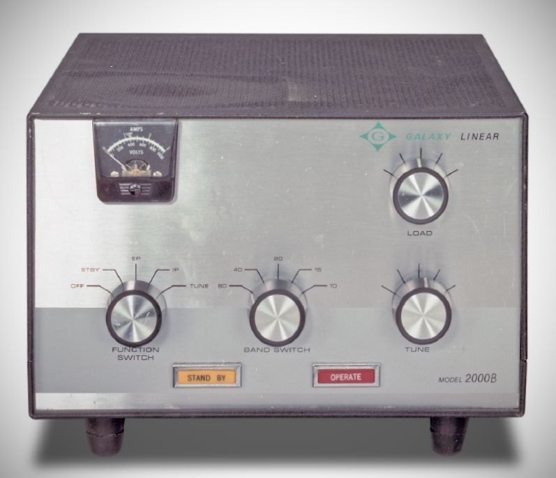
The Galaxy 2000+ is a compact HF linear amplifier manufactured by Galaxy Electronics in the mid-1960s. The amplifier was designed to provide high power output across the 80 through 10 meter bands at a relatively modest price.
The setup consists of the tabletop amplifier unit measuring 6 x 10 1/4 x 11 1/2 inches and a matching external power supply measuring 7 x 9 1/2 x 7 1/2 inches. The power supply weighs 30 lbs and connects via a 5-foot interconnecting cable.
Designed for use with a 100-watt exciter. On SSB, it delivers a PEP input of over 2000 watts (producing roughly 1300 watts PEP output). On CW and RTTY, it provides up to 1000 watts DC input (yielding approximately 600 watts output).
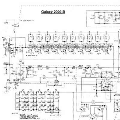
The amplifier utilizes ten 6HF5 TV horizontal-deflection tubes connected in parallel using grounded-cathode circuitry. Operating the tubes in parallel at a low plate potential of 800 volts allowed high power output without requiring expensive high-voltage components. ⚠️ These tubes were changed to ten 6BL6s in the "B" version on the amplifier.
Swamped Untuned Input: The grid-input circuit is untuned and connected directly to the tube grids. The grids are shunted by a 50-ohm, 100-watt Globar non-inductive resistor. This heavy swamping provides a proper load for the exciter and maintains stability without needing neutralization.
10/15 Meter Compensation: On 10 and 15 meters, an inductor is switched in shunt across the input to counteract the high capacitive reactance of ten parallel tube grids. Parasitic suppressors are installed in each individual tube plate lead.
Because ten parallel tubes operated at low voltage and high current produce an unusually low plate load impedance, a standard Pi-network would require impractically large tuning/loading capacitors and a tiny tank coil capable of handling excessive circulating currents.
To overcome this, the Galaxy 2000+ employs a capacitive impedance-divider network. The tubes connect across a lower-impedance portion of a higher-impedance tank circuit, functioning similarly to an inductor tap.
The 10–15 meter section of the tank coil is constructed from 1/4-inch silver-plated copper tubing, while the lower frequency bands use #14 wire.
Built-in Low-Pass Filter: Includes a two-section M-derived TVI filter that attenuates all frequencies above 40 MHz. Screw-driver adjustable trimmer capacitors accessible from the side cabinet allow notch-tuning for specific TV channels (factory set for channels 3 and 6).
Cooling: Forced-air cooling is supplied by an internal blower fan, assisted by ventilated perforated metal cabinet panels and large chassis cutouts.
The separate power supply utilizes silicon rectifiers and a single heavy-duty power transformer with primary windings configurable for 115V or 230V AC operation (230V recommended due to peak primary currents up to 20A).
Mode Selection: Operating modes are selected via a jumper plug on the power supply:
SSB Mode: Connects a 200V supply in series with a 600V supply to deliver 800V plate potential and 200V screen potential. Filter capacitance for the high-voltage rail is provided by four electrolytic capacitors in series-parallel (300 µF total).
CW/RTTY Mode: Reconfigures the supply to ground the negative side of the 600V source, limiting plate potential to 600V to keep continuous key-down power within legal limits.
References
Review. CQ, Jan 1967, p. 17.