Note
QST, Feb 1969, p. 107.
QST, Aug 1971, p. 116. (GT-550A, after Galaxy's merger with Hy-Gain)
QST, Jan 1972, p. 144.
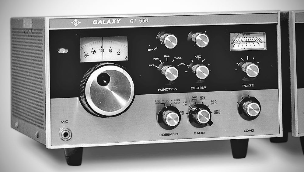
The GT-550 was a redesign and repackaging of the Galaxy V Mk III transceiver. It made greater use of sold-state devices than its predecessor. SSB PEP input increased to 550 watt. Requires the AC-400 AC power supply or the G-1000 DC power supply.
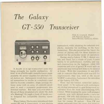
The Galaxy GT-550 is a classic, high-power amateur HF transceiver designed for operation on the 80 through 10-meter bands. It was known as one of the "hottest" transceivers of its era due to its robust 550-watt PEP input power. The GT-550 features a hybrid circuit design, utilizing a combination of solid-state components and vacuum tubes to maximize performance and efficiency. It is housed in a mar-resistant black crackle cabinet with a stylish two-tone brushed aluminum front panel.
550 watts sounds like a lot of power, but remember that that number is *input* power. QST found that on a Bird model 43 wattmeter, power out is about 130 watts CW in the TUNE position of the FUNCTION switch, 200 watts CW in the CW position, and 260 watts PEP SSB in the PTT position. For the ten meter band these figures dropped to, in the same order, 90 watts, 140 watts, and 160 watts PEP.
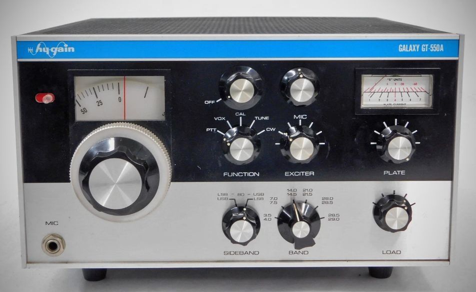
The transition from the Galaxy GT-550 to the GT-550A represents a series of iterative improvements by Hy-Gain Electronics to refine the transceiver's performance. While both units maintain the same fundamental hybrid architecture, the "A" model introduces several technical and functional enhancements.
The most prominent differences between the two models are as follows:
– Mechanical and Frequency Stability: The tuning mechanism was improved to feature a smooth, ball-driven assembly. This system provides a more precise five-kilocycle readout display and maintains a constant tuning rate across all bands. Additionally, the VFO in the 550A was engineered for superior temperature stability, drifting less than 100 Hertz per 15 minutes after a brief warm-up period.
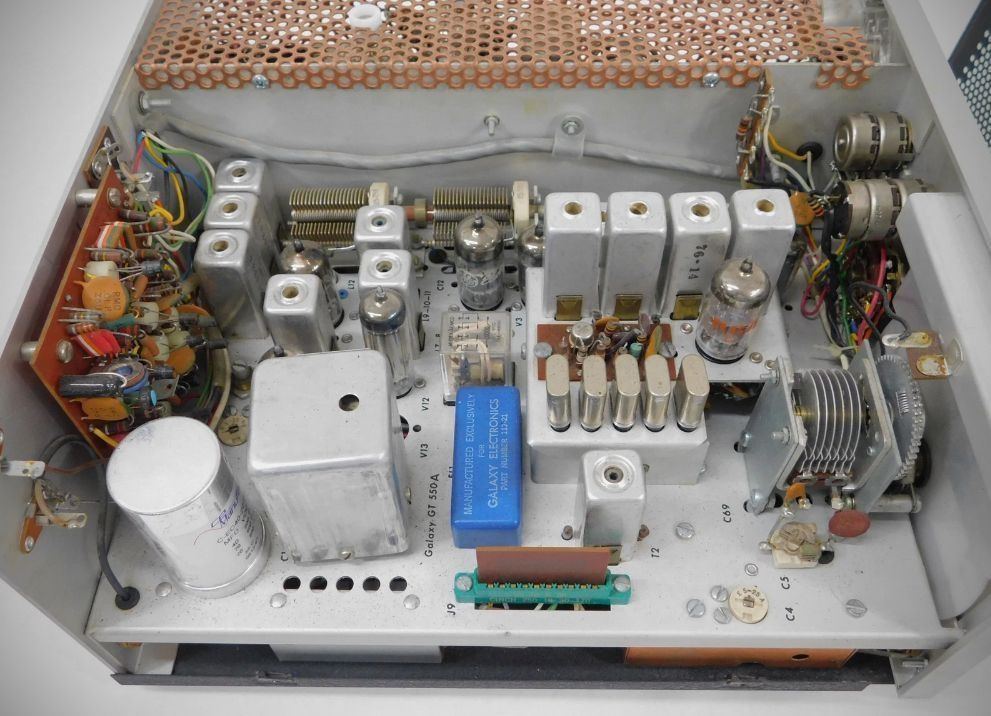
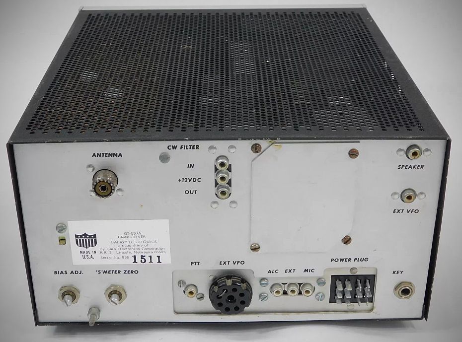
– Selectivity: The "A" model utilizes a six-pole 9.0 MHz crystal lattice filter to provide optimum selectivity for single sideband operation. For operators who prioritize CW, the GT-550A also supports a dedicated F3 CW filter accessory—a plug-in 300 Hz audio filter that significantly narrows the bandwidth to reduce interference.
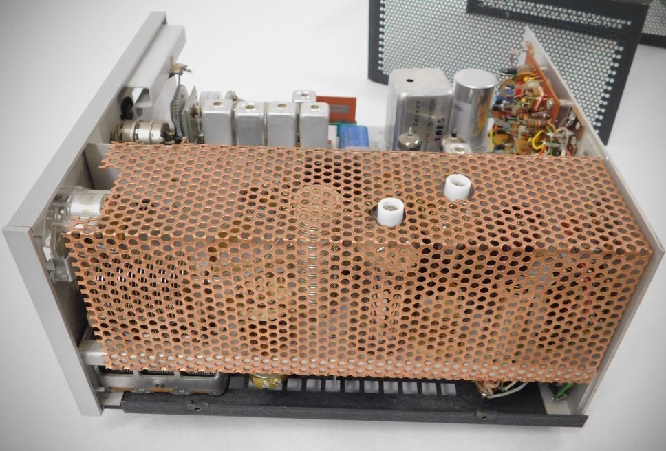
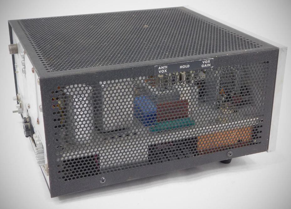
– Expanded Accessory Integration: The internal layout and rear panel were updated to better accommodate a growing ecosystem of accessories. This includes dedicated sockets and internal provisions for the VOX-35C voice control system and the CAL-250 25 KHz crystal calibrator. These modules can be controlled directly from the front-panel function switch, allowing for seamless transitions between manual PTT, voice-controlled SSB, and dial calibration modes.
Features
– Hybrid Circuitry: Features a mix of semiconductors and tubes (18 transistors, 9 diodes, and 13 tubes (12 in the GT-550)), with solid-state components outnumbering tubes by more than two to one.
– Final Amplifier: Uses a pair of parallel-connected 6LB6 TV horizontal-sweep tubes operated in Class AB1.
– High Selectivity: Equipped with a sharp 9 MHz, 2.1 kHz crystal filter with a better than 1.8:1 shape factor to suppress unwanted sidebands.
– Selectable Sideband: Allows sideband switching without a 2 kHz frequency jump.
– Shifted Carrier CW: Prevents "leap-frogging" with another transceiver while operating in CW mode.
– Automatic Level Control (ALC): Built-in ALC limits voice peaks and reduces the possibility of overdriving and distortion.
– CW Side-tone: Built-in audio side-tone allows for CW monitoring through a speaker or headphones.
– Versatile Keying: Supports manual keying for SSB/CW, as well as VOX and break-in CW operation (with an optional plug-in VOX accessory).
– Single-Scale VFO Dial: Designed for smooth tuning and easy frequency interpolation.
Specifications
General
– Frequency Range (6 Bands):
3.5 - 4.0 MHz (80 meters)
7.0 - 7.5 MHz (40 meters)
14.0 - 14.5 MHz (20 meters)
21.0 - 21.5 MHz (15 meters)
28.0 - 28.5 MHz (10 meters)
28.5 - 29.0 MHz (10 meters)
– Modes of Operation: SSB (Upper and Lower) and CW
Transmitter
– Input Power: 550 watts PEP on SSB; 360 watts on CW
– Output Power: ~250 watts (SSB); ~160 watts (CW)
– Carrier Suppression: Stable, -45 dB
– Unwanted Sideband Suppression: Better than -55 dB
– Antenna Impedance: Designed for non-reactive loads between 40 and 100 ohms (SO-239 connector)
Receiver
– Receiver System: Single conversion superheterodyne (9 MHz IF)
– Sensitivity: 0.5 µV for 10 dB S+N/N ratio
– External Speaker Connector: Phono (RCA), 8 ohm impedance
Tubes
The tube lineup is identical in each version with two exeptions: In the 550A, V12 was changed from an 0A2 to an 0B2, and an additional tube was added– V13 is an 0C2.
GT-550A (12): (1) 12BZ6, (1) 6HG8, (1) 6EW6, (1) 12BA6, (1) 6GX6, (1) 6KE8, (1) 12AT7, (1) 6EJ7, (1) 6GK6, (2) 6LB6, (1) 0A2
GT-550 (13): (1) 12BZ6, (1) 6HG8, (1) 6EW6, (1) 12BA6, (1) 6GX6, (1) 6KE8, (1) 12AT7, (1) 6EJ7, (1) 6GK6 , (2) 6LB6, (1) 0B2, (1) 0C2.
Accessories include the RF-550 wattmeter, the SC-550 speaker, and the LA-550 kilowatt linear amplifier.
And see QST, Aug 1972, p. 112 for an unspecified rotator system. Also shown in QST, Jan 1972, p. 142, but not seen in QST, Feb 1973, p. 113.
References
Review. 73, May 1969, p. 48.
Brief description. Electronics World, May 1969, p. 89.
Brief description. Popular Electronics, May 1969, p. 22.
Brief description. Ham Radio, Jun 1969, p. 71.