Note
QST, Mar 1968, p. 127.
QST, Nov 1971, p. 133.
QST, Mar 1973, p. 156.
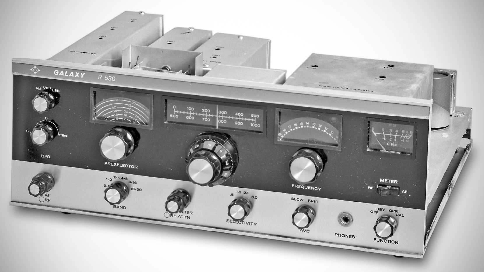
The Galaxy R-530 (later produced under the Hy-Gain brand following their acquisition of Galaxy Electronics) is a high-end, solid-state general coverage communications receiver manufactured between 1968 and 1974. Targeted at advanced shortwave listeners, commercial operations, and demanding radio amateurs, it was an ambitious design that offered digital-like analog tuning accuracy at a time when most receivers were still utilizing vacuum tubes.
The R-530 fully solid-state and synthesized. It used modular construction, some of which can be seen in this “topless” photo. The R-530 covered .5–30 MHz in 500 kHz ranges and had 1 kHz calibration on its tuning dial. The standard 9 MHz IF filter was 2.1 kHz, with .5, 1.5, and 5 kHz filters available as options.
Specifications
– Receiver Type: RF Superheterodyne, dual conversion, solid state.
– Frequency Range: 0.5 to 30 MHz continuous.
– Frequency Readout: 1 kHz over the entire 500 kHz tuning range of the PTO.
– Frequency Stability: From turn-on no more than 100 Hz, including 20% line voltage variation.
– Calibration Accuracy: 1 kHz with 50 kHz calibrator.
– Backlash: Less than 100 Hz.
– Metering:
RF: Calibrated 0 to 80 dB above 1 microvolt.
AF: Calibrated -6 to +4 dBm (600 ohm balanced line).
– AGC: Selectable FAST or SLOW.
Attack time: Less than 5 milliseconds.
Slow release time: 2 seconds.
Fast release time: 500 milliseconds.
Output change: Less than 6 dB output change from 1 to 30,000 microvolts.
– Sensitivity (for 6 dB signal plus noise to noise ratio):
SSB: 0.1 microvolts
CW: 0.05 microvolts
AM: 0.5 microvolts
– Selectivity: 2.1 kHz crystal lattice filter, 1.8:1 shape factor, SSB. Optional front-panel selectable filters available for CW (0.5 kHz) and AM (5.0 kHz).
– Inter-Modulation Distortion: 3rd order suppressed more than 50 dB.
– Front-end Overload: 0.1 volt for 10% distortion (On Signal).
– RF Signal Attenuator: Variable line attenuator provides 0–20 dB attenuation of signal before reaching receiver front-end.
– Harmonic/Spurious Response: All spurious and harmonics suppressed more than 50 dB.
– Noise Blanker: Adjustable for optimum performance on SSB and CW.
– Modes: AM, CW, SSB (Selectable USB & LSB), and RTTY. Variable BFO utilized in CW mode tunable ±1 kHz.
– Audio Output Level: More than 1 watt with less than 10% distortion.
– Audio Response: 250 to 3.0 kHz $\pm 3\text{ dB}$.
– Audio Output Provisions: Speaker (8 ohms), Line (600 ohms balanced), Headphone.
– Calibrator: 50 kHz.
– Antenna Input: 50 ohms unbalanced.
Power Requirements: 115/230 VAC, 50–60 Hz, 24 watts, or 18 VDC maximum source drain 600 mA.
References
Brief description. Popular Electronics, Mar 1968, p. 22.
Brief description. Ham Radio, Apr, p. 88.
Brief description. Popular Electronics, Oct 1968, p. 54.