Note
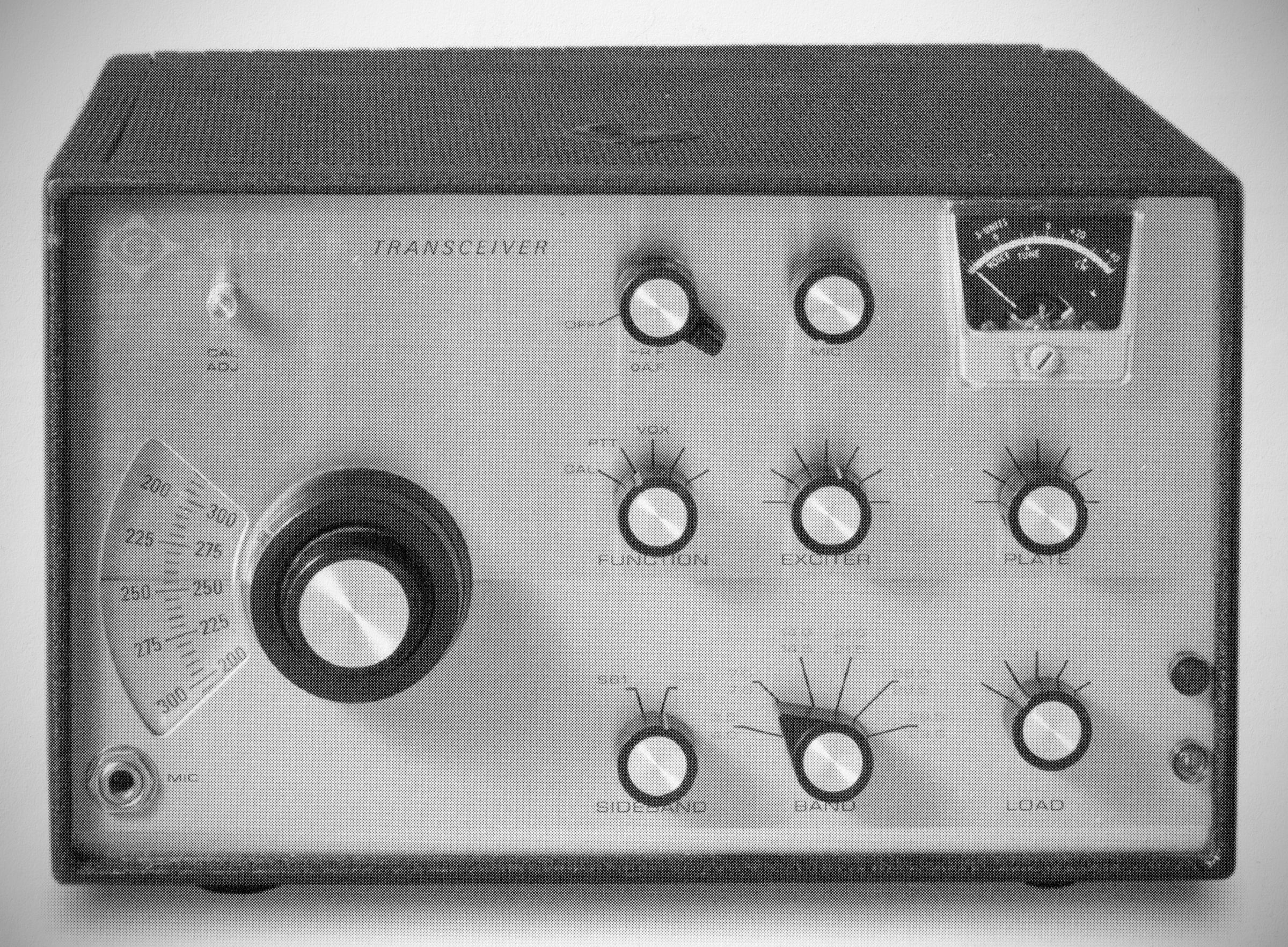
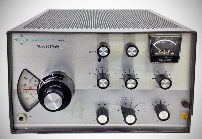
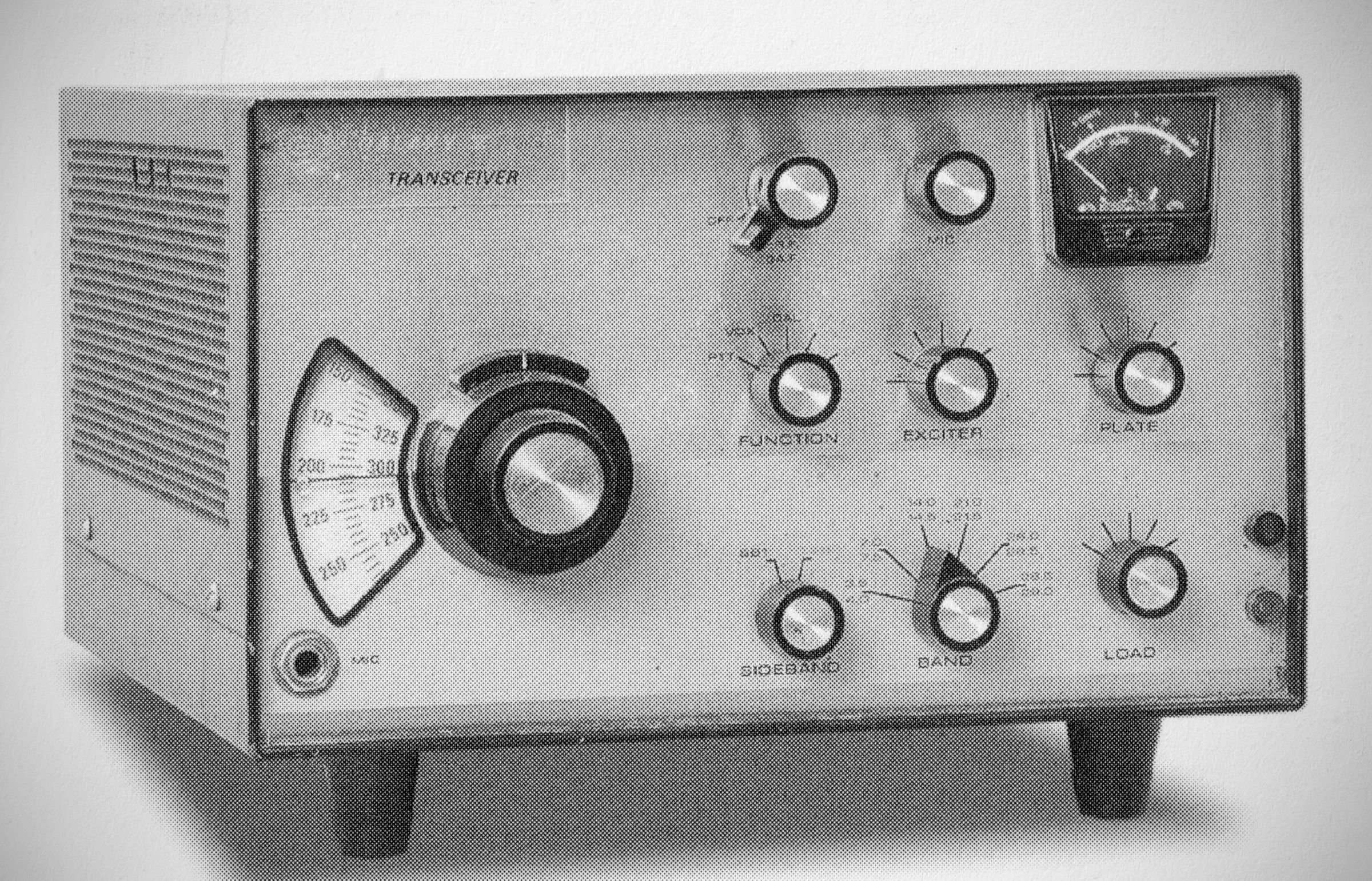
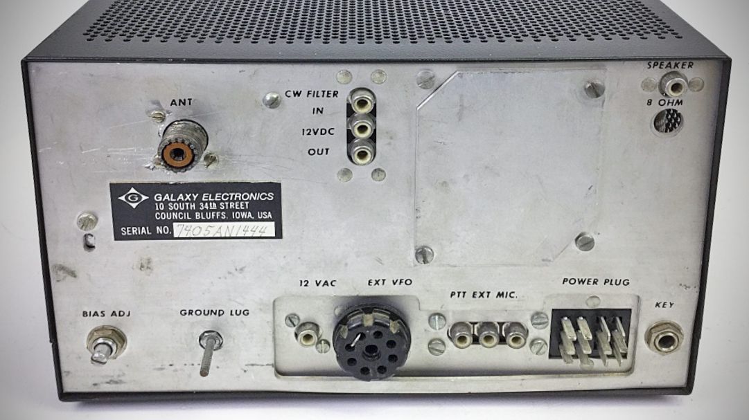
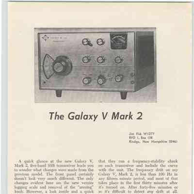
Galaxy V
QST, Jun 1964, p. 117.
Allied Radio catalog 1966 (copyright 1965), p. 357.
QST, Feb 1967, p. 121. (Mark 2)
QST, Jun 1968, p. 123. (Mark 3)
Galaxy Electronics was formed by World Radio Laboratories' Leo Myerson, W0GFQ, in 1962. The Galaxy V was a 300 watt PEP transceiver covering 8D-10 meters. The VOX as well as the receiver's audio and AVC circuits were solid-state.
The Mk II version of the Galaxy V introduced a solid-state VFO and changed the final tubes to a pair of 6HF5s. Power input increased to 400 watts PEP. Also added was a new vernier logging scale, sidetone audio, a break-in option, and a new CW filter.
The Galaxy V MK Ill upped the horsepower of their Galaxy V transceiver by changing the final tubes to a pair of 6LB6s. The grid/ cathode circuit for driving the finals was redesigned and the ALC circuit improved. SSB input power was 500 watts.
Specifications (Galaxy V)
– Frequency Coverage:
3.5 to 4.0
7.0 to 7.5
14.0/14.5
21.0 to 21.5
28.0 to 29.0 MHz. (The 10 meter band is covered in two 500 kHz. ranges, factory supplied 28.0 to 28.5 and 28.5 to 29.0 MHz. It is possible, by the installation of optional crystals, to cover other segments of 28.0 to 30.0 MHz.)
– VFO: Linear capacity tuned VFO; tunes 5.0 to 5.5 MHz. at all times. 9.0 MHz. crystal plus VFO frequency covers 20 meters, 9.0 MHz. crystal minus VFO frequency covers 75-80 meters, VFO plus crystal osc. mixed in premixer and 9.0 MHz. crystal covers the 40-15-10 meter bands.
– Tuning Ratio & Dial: 36:1 planetary drive with 2:1 gear drive (spring loaded for anti-backlash) gives 72:1 slow tuning with fast tuning outer knob provided. Circular dial has over 9 inches of bandspread. 5 KHz. dial marks can be interpolated to nearly 1 KHz.
– Stability: Stability of the VFO is extremely good with drift of less than 100 cps. in any 15 minute period after warmup. Less than 100 cps. frequency change for 10% change of line voltage.
– Sideband Selection: Upper or lower sideband, panel selected.
– Keying Method: PTT (or VOX with accessory).
– Sideband Suppression: In excess of 55 DB.
– Carrier Suppression: In excess of 45 DB.
– Audio Response: Overall audio response down 6 DB at 300 and 2,400 cps.
– Output Impedance: Nominal 50 Ohms (40-100 Ohms resistive), adjustable PI-net.
– ALC used to obtain maximum power and minimize flattopping, as well as increasing talk-power.
– Microphone Input: High impedance microphone input.
– Sensitivity: Less than 1/2 microvolt produces better than 10 DB S/N.
– AGC: Full AGC. Audio varies less than 6 DB for 60 DB change. Two speed AGC provides fast attack-fast release for signal variation of 20 DB and slow attack-slow release for greater signal variation. Essentially free from pops and pumping over 40 DB range and free over any range with proper use of RF gain control.
– Antenna Input Impedance: Nominal 50 Ohms.
– Speaker Output Impedance: 4 to 8 Ohms, nominal.
– Audio Power Output: 3 watts at low distortion.
Tube Lineup (Galaxy V)
– 12BZ6 (Receiver RF Amplifier)
– 6HG8 (Receiver Mixer)
– 12BA6 (1st IF Amplifier)
– 12BA6 (2nd IF Amplifier)
– 6GX6 (Product Detector / Oscillator)
– 6EA8 (VFO / Cathode Follower)
– 12AT7 (Balanced Modulator)
– 6EJ7 (Transmitter Mixer)
– 6GK6 (Driver Stage)
– 6HF5 (Power Amplifier Final)
– 6HF5 (Power Amplifier Final)
– 0A2 (Voltage Regulator)
– 0A2 (Voltage Regulator)
– 6EA8 (Microphone Amplifier / Audio)
– 6EA8 (Heterodyne Oscillator / Converter)
Power Requirements
800 VDC @ 400 Ma. with 10% regulation for 80 to 400 Ma. swing.
350 VDC @ 200 Ma. with 10% regulation.
–100 VDC @ 35 Ma.
12.6 VAC/DC @ 5 Amp.
12.6 VDC @ 1 Amp.
References
Review. 73, Apr 1965, p. 78.
Review (Mark 2). 73, Jul 1967, p. 94.