Note
QST, Sep 1957, p. 101.
QST, Nov 1957, p. 159.
Radio Amateur's Handbook, 1958, p. 85.
Allied Radio catalog 1958 (copyright 1957), p. 272.
QST, Jul 1958, p. 105.
QST, Apr 1960, p. 168.
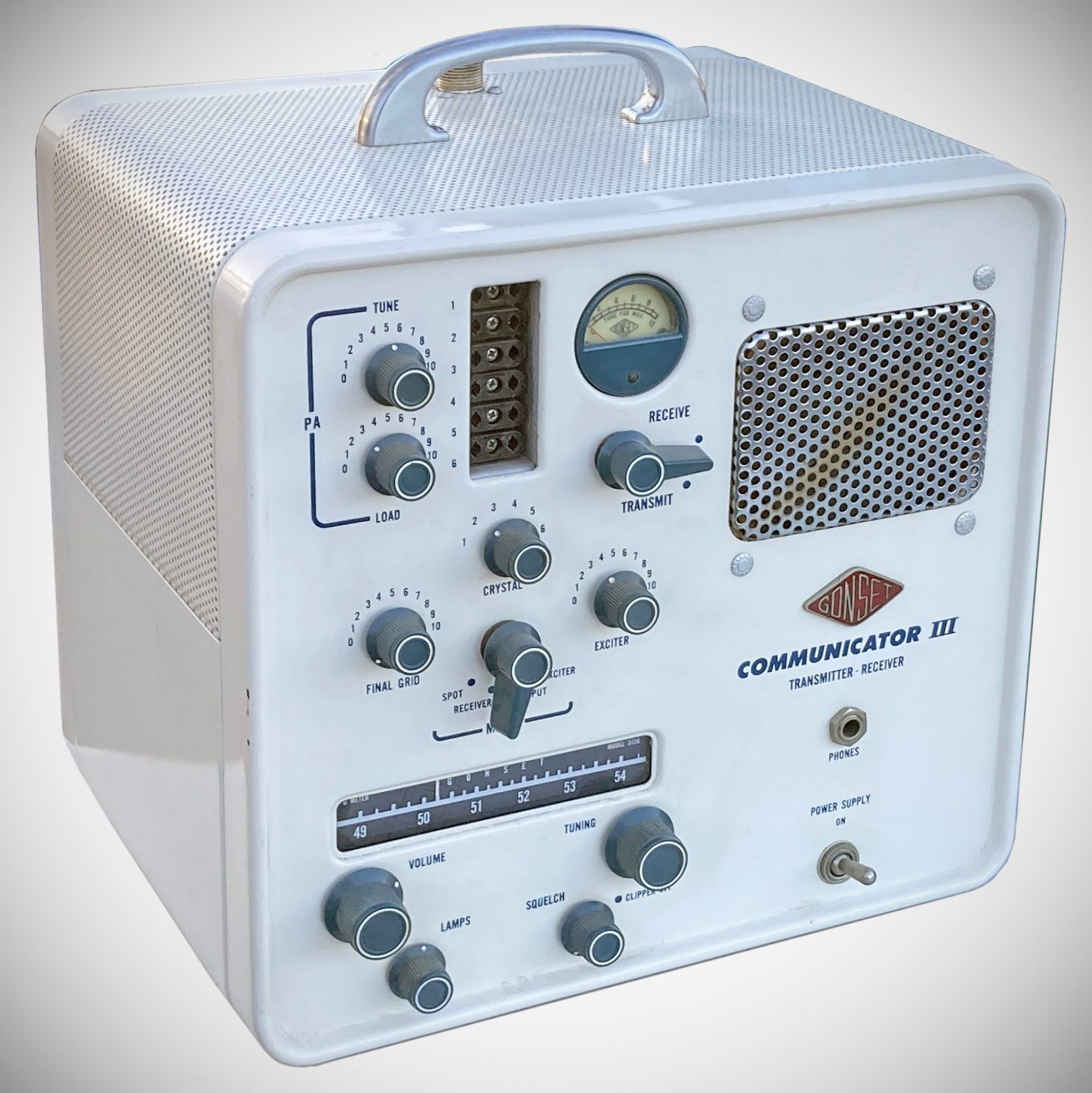
Released in September 1957, the Communicator III was a significant redesign. The most notable change may have been the tri-voltage power supply. The unit could now be powered by 115 VAC, 12 VDC, or 6 VDC. No more separate versions.
Other changes includes:
– full support for PTT (you could still use the front panel lever if you wanted)
– receiver includes a new low noise X155 RF tube in cascode
– AVC
– improved IF selectivity
– slide rule tuning dial
– knobs on all the controls
– a meter to replace the magic eye
– provision for six crystals
– silicon diodes in the power supply
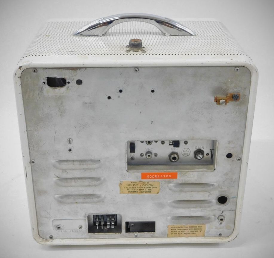
The Communicator III was made in seven versions for amateur, commercial, aeronautical, and government applications. Visually, all of them looked the same as in the lead photos, except for the civil defense versions, which were yellow.
Civil defense models included a number of unspecified changes to make them compliant with Federal Civil Defense Administration (FCDA) requirements, to make them available for purchase with federal funding. Beyond the bright yellow cabinets, they are In most respects identical to the 2- and 6-meter versions of the Communicator III series.
The versions include:
3133 - 2 meters
3133 CD - 2 meter FCDA civil defense
3133 CAP - 2 meter Civil Air Patrol
3136 - 6 meters
3136 CD - 6 meter FCDA civil defense
3139 - 112 to 132 MHz (ground to air)
3215 - 132 to 152 MHz
3220 - 2 meter "package" that includes the 3133 and 3211 amplifier
3231 - 6 meter "package" that includes the 3136 and 3212 amplifier
Model 3215 is a curious version since that portion of the spectrum is occupied by virtually all user communities--amateur, commercial, aeronautical, and government (including the military).
Model 3129 "Ground to Air" Communicator uses a three-way power supply permits operation from 6 or 12 volt vehicular storage battery or from 115V AC mains. Crystal controlled transmitter supplies full 6-7 watts output power with AC or DC power sources. Superhet receiver has low noise X-155 RF in a cascode circuit, selective I-F, noise clipper, adjustable "squelch". Receiver is continuously tunable from 112 to 132 MHz. Operation is simple, non-technical. Unit is same size and weight as other comparable Communicator III models. Can be used with integral whip or remote antenna and 52 ohm coaxial line. Size and appearance same as model #3133.
Specifications for all models
General
– Vibrator: Mallory 1501 (6 volts) for all models.
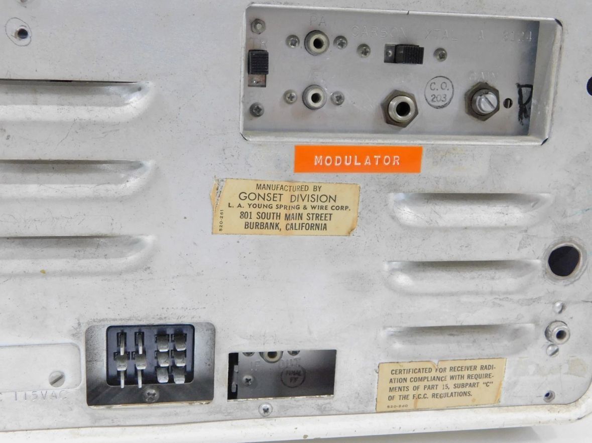
– PA Voice Coil / VFO / I.F. Out: Type 13A or M-93 Cinch phono plug.
– Headphones: Low impedance (600 ohm) type recommended for automatic speaker muting. High impedance phones will work with less volume.
– Public Address (PA): Connects to a 4 to 8-ohm voice coil of an external trumpet-type speaker.
Receiver & Transmitter
– RF Output Power: about 6 watts
– Mode: AM
– Duty Cycle: Intermittent service only; "transmit" time must not exceed 10 minutes during any 20-minute period.
– Crystals: Fundamental type in FT-243 type holder.
– Microphone Compatibility: Push-to-talk single button carbon (telephone type F2 or T-1 recommended), or high output ceramic, crystal, or high impedance dynamic/controlled reluctance (minus 48 to 55 db), ceramic crystal microphones (e.g., Astatic M-101) can be used if not down more than 55 db.
– Squelch: Carrier-actuated with a biased series-gate diode; can gate on a change as small as 0.1 volt.
– Modulator: Class A single-ended beam tetrode with integral speech clipping.
– Modulation: Held to approximately 85-90% to avoid "splatter" from negative peak clipping.
– Tuning Indicator: Front panel meter serves as an "Exciter" or "Output" indicator for the transmitter and a relative carrier strength indicator for the receiver.
– Receiver Noise Figure: Approximately 5 db.
– Selectivity: Five I-F transformers are used for a high "shape factor" (low ratio of skirt to nose selectivity).
– Antenna Requirements: Designed for a 50 or 70-ohm coaxial line with low standing wave ratio, or a quarter-wave whip for frequencies above 100 Mc.
Power Input: Low voltage DC or 115 volts AC (60 to 400 cycles) using appropriate power cords. 12-volt models are designed for 13.5 volt input. All versions are factory wired for 12 VDC, but are easily changed to 6 VDC.
Power Drain:
Transmit: 95 watts or 15 amps when using a 6-volt supply.
Receive: 75 watts.
RF Power Amplifier: 2E26
Transmitter/Exciter: 6BZ8