Note
QST, Jul 1960, p. 113.
Allied Radio catalog 1962 (copyright 1961), p. 280.
QST, May 1962, p. 103.
Allied Radio catalog 1963 (copyright 1962), p. 285.
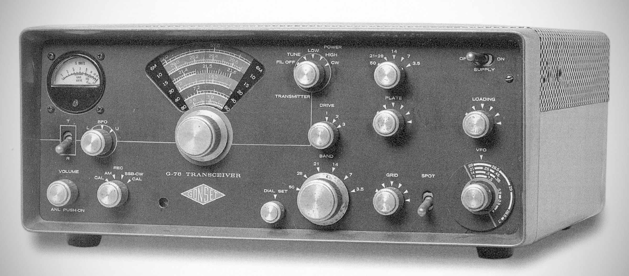
The Gonset G-76 (Model 3338) is a compact, multi-band amateur radio transceiver manufactured by the Gonset Division of Young Spring & Wire Corporation in Burbank, California. Designed for both fixed-station and mobile amateur radio operations, the G-76 combines a high-power transmitter and a double-conversion receiver into a single compact (by the standards of the day) cabinet.
Gonset's mobile transmitter/receiver ran 100 watts input AM and 120 watts CW on 80-6 meters.
The transmitter and receiver had separate VFOs, and the transmitter was limited to crystal-controlled operation on 6 meters. Its final amplifier was a 6DQ5 with a pi-network.
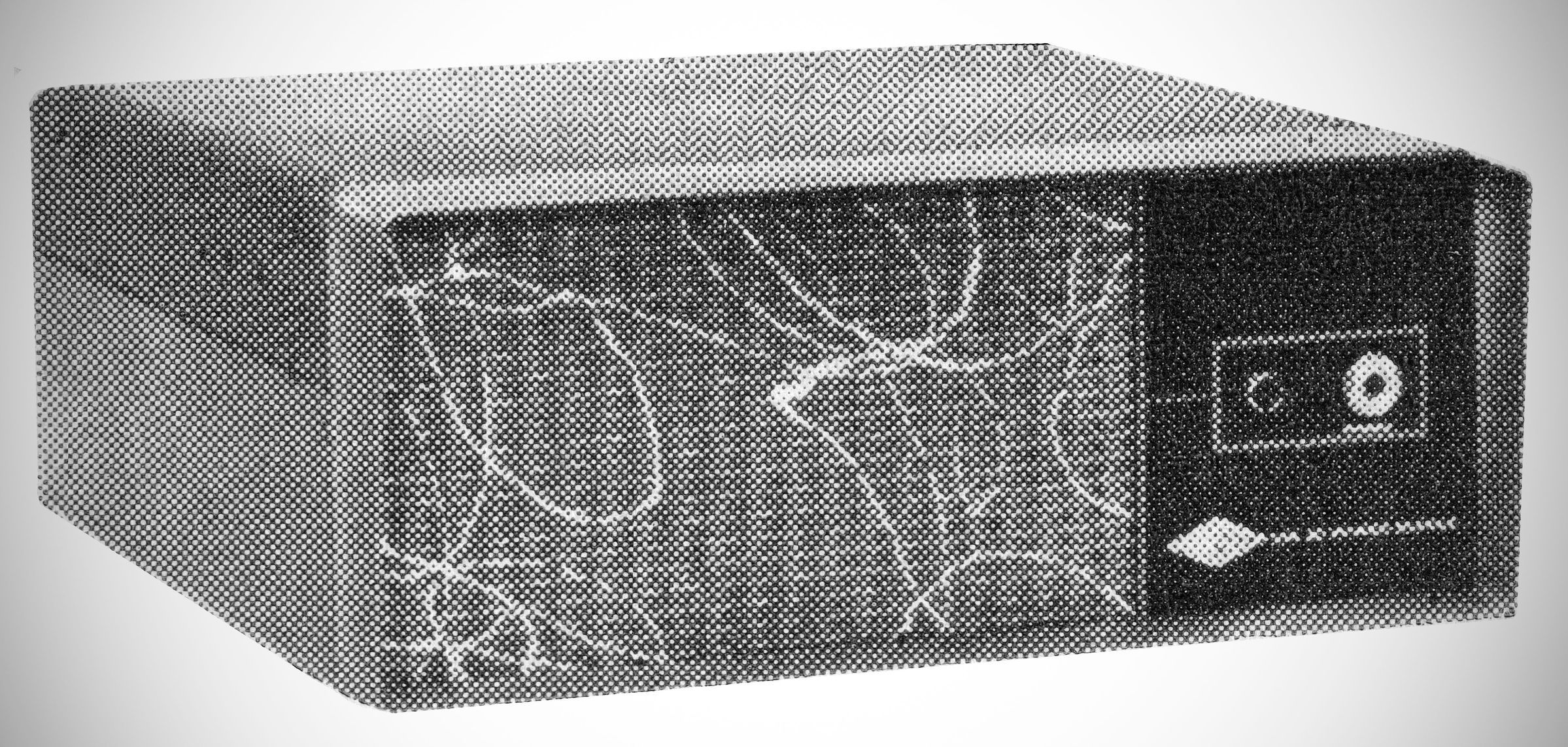
The G-76's receiver was double conversion with IFs at 2065 and 262 kHz. It had a separate transistorized 12 VOC power supply for mobile operation and a combination 117 VAC power supply/speaker cabinet for home use.
Features: Includes an automatic noise limiter (switched via a push-pull switch on the volume knob), a dial set control for minor calibration corrections, and support for an optional plug-in 100 Kc crystal calibrator (Gonset Model 3269). Audio output is rated at 2.5 watts into a 3.2-ohm speaker.
Specifications
Frequency Coverage: Covers six amateur bands: 80 meters (3.5–4.0 MHz), 40 meters (7.0–7.3 MHz), 20 meters (14.0–14.35 MHz), 15 meters (21.0–21.45 MHz), 10 meters (28.0–29.7 MHz), and 6 meters (50.0–54.0 MHz).
– Circuit Architecture: Double-conversion superheterodyne configuration.
– Intermediate Frequencies: First IF is 2065 kHz; second IF is 262 kHz.
– Sensitivity: Approximately 1 microvolt at 50 ohms for a 6 dB signal-plus-noise to noise ratio.
– Selectivity: Nominally 3 Kc bandwidth at 6 dB down; 14 Kc or less at 60 dB down.
– Modes: AM, CW, and SSB.
– Audio Output: 2.5 watts into a 3.2-ohm speaker load.
– Noise Limiter: Automatic type, switchable from the front panel volume control.
– Power Input: 100 watts on amplitude-modulated (AM) phone and 120 watts on CW.
– Frequency Control: VFO tuning via planetary vernier drive for 80 through 10 meters. 6-meter operation requires crystal control (using 8.334 to 9.0 Mc crystals) or an external VFO. Crystal control is also switch-selectable for HF bands.
– Output Network: Pi-matching system designed for 50-ohm unbalanced coaxial lines.
– Output Network: A pi-matching network provides output matching to an unbalanced 50-ohm coaxial load via a standard UHF SO-239 connector.
Tube Lineup
The transceiver uses a total of 18 tubes in the main unit, plus 2 tubes in its matching AC power supply:
– 12BY7A: Oscillator
– 12BY7A: Multiplier
– 6DQ5: Power Amplifier (Final)
– 6DQ6B: Modulator
– 6DQ6B: Modulator
– 12AQ5: Clamper Tube
– 0B2: Screen Control / Voltage Regulator
– 6BZ6: RF Amplifier
– 6U8A: First Mixer / High-Frequency Oscillator
– 6BE6: Second Converter
– 12BA6: First IF Amplifier
– 12BA6: Second IF Amplifier
– 12AL5: Detector, AVC, & Automatic Noise Limiter (ANL)
– 12AU7: Audio Amplifier & Beat Frequency Oscillator (BFO)
– 0A2: Voltage Regulator
– 12AX7: Microphone Amplifier / Audio Stage
– 6CM6: Audio Output / Modulator Driver
– 0B2: Voltage Regulator
Optional 100 Kc Crystal Calibrator (Gonset Model 3269)
– 6AU6
Model 3349 AC Power Supply
– (2) 5R4GYA: High Voltage Rectifier
Power Requirements
The G-76 requires external power provided by one of two matching power supply units:
Model 3349 AC Power Supply: Operates from 117 VAC (drawing 3 amps on transmit and 1.5 amps on receive) and delivers 600 VDC at 250 mA, 265 VDC at 120 mA, and 12.6 VAC at 5 amps for filaments. It includes a built-in speaker and front-panel headphone jack.
Model 3350 DC Power Supply: Designed for 13.4 VDC mobile installations, providing 600 VDC at 300 mA and 250 VDC at 130 mA.
References
Review: CQ, Nov 1961, p. 64.