Note
QST, Aug 1958, p. 107.
CQ, Aug 1958, p. 11.
Allied Radio catalog 1959 (issued 1958), p. 378.
QST, Mar 1962, p. 160. (close out)
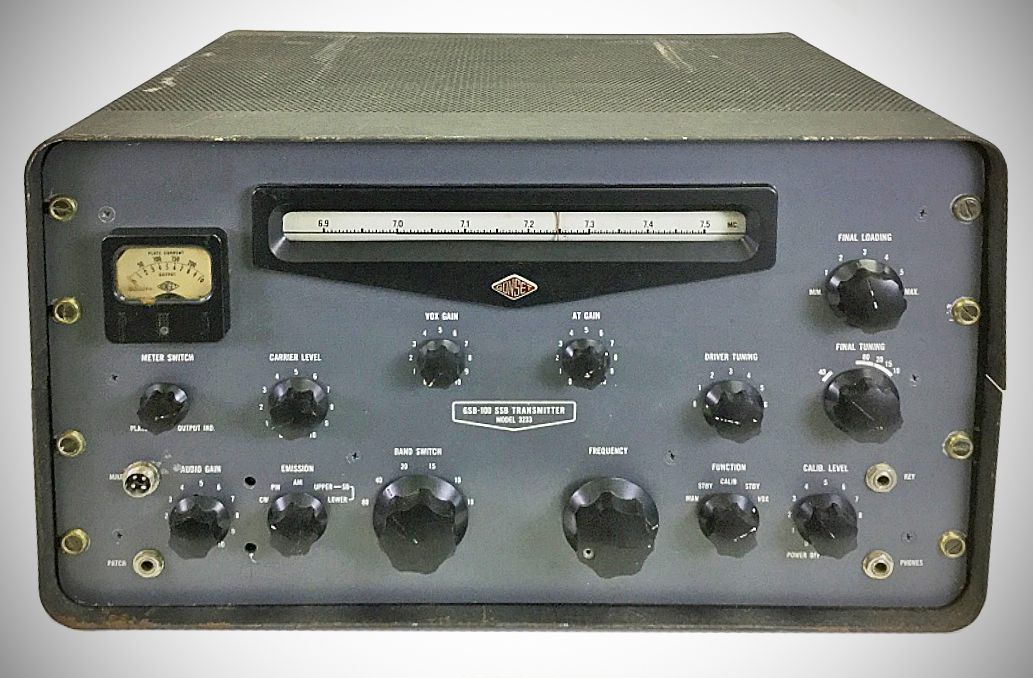
The Gonset GSB-100 is a SSB) transmitter that can also be utilized as an exciter for a linear amplifier, such as the Gonset GSB-101. In addition to SSB operation (both upper and lower sidebands), the unit supports AM, CW, PM (Phase Modulation / narrow-band)
It features built-in VOX anti-trip for SSB, AM, and PM modes.
Signal generation occurs at a reference frequency of 9 MHz via a crystal oscillator. Sideband suppression and carrier minimization are achieved through a combination of crystal filtering, phasing circuitry, and a specialized notch filter, ensuring long-term suppression stability without requiring frequent manual adjustments.
The unit utilizes a 6DQ5 power amplifier tube in its final stage.
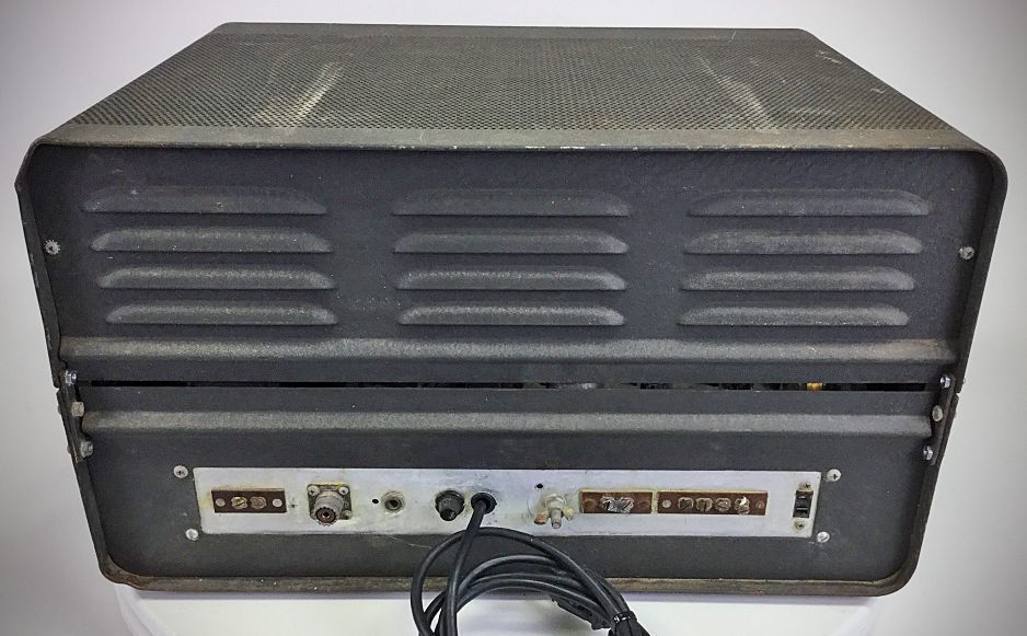
The rear chassis includes terminal strips for receiver speaker muting, remote transmit-standby switching, and a dedicated bias line designed to automatically cut off connected linear amplifier tubes during receive periods.
Specifications
– Power Input to Final Amplifier:
SSB: 100 watts PEP
CW: 100 watts
PM: 75 watts
AM: 50 watts
– Power Output: 65 watts PEP into a nominal 50-ohm unbalanced load (matching range of 30–200 ohms).
– Frequency Control: A built-in VFO operating from 5.0 to 5.6 MHz. All other internal oscillators are crystal-controlled to maximize stability.
– Frequency Stability: Maximum of 250 Hz over a two-hour period starting from a cold start.
– Suppression Levels: Features a carrier suppression of -60 db and unwanted sideband suppression of -40 db during SSB emission. Spurious emission is rated better than 50 db.
Frequency Range
The transmitter features complete bandswitching across six distinct 600 KC frequency segments:
Band 1 (80 Meter): 3.4–4.0 MHz
Band 2 (40 Meter): 6.9–7.5 MHz
Band 3 (20 Meter): 14.0–14.6 MHz
Band 4 (15 Meter): 21.0–21.6 MHz
Band 5 (10 Meter): 28.5–29.1 MHz
Band 6 (10 Meter): 29.1–29.7 MHz (Standard factory units are shipped with this coverage, though an optional crystal can replace Band 6 to cover 28.0–28.6 MHz for 10-meter CW operation).
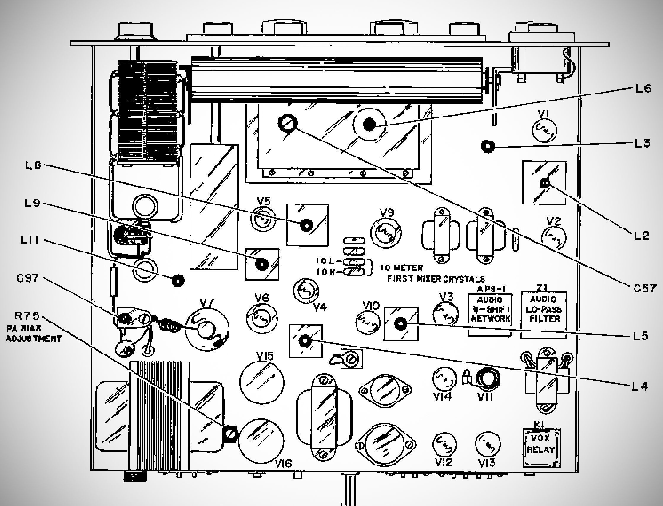
Tube Lineup (16 total)
– 12AX7 Microphone Amplifier / Second Audio Amplifier
– 6AZ8 Audio Frequency Driver / 9 MHz Crystal Oscillator
– 12AU7 Audio Frequency Modulator
– (2) 6AH6 Amplifier First Mixer and Second Mixer
– 12BY7A RF Driver
– 6DQ5 RF Power Amplifier
– 9006 RF Output Voltage Rectifier
– 12AU7 VFO / VFO Cathode Follower
– 12AT7 High-Frequency Crystal Oscillator
– 0A2 Voltage Regulator
– 12AX7 Voice Control Audio Amp / Anti-trip Audio Amp
– 12AT7 Second Anti-trip Audio Amp / Relay Control Amp
– 6AL5 Voice Control Audio Rectifier / Anti-trip Audio Rectifier
– (2) 5U4GB) High Voltage and Low Voltage Rectifiers
– (4) 1N34A Germanium Balanced Modulator Diodes
– CR5 (unspecified) Selenium Bias Rectifier Diode
Primary Power: 117 VAC, 50/60 Hz.
References
Review. CQ, May 1959, p. 44.
Review. QST, Sep 1959, p. 44.
Adding Crystal Control. 73, Jun 1962, p. 54.