Note
QST, Aug 1958, p. 107.
CQ, Aug 1958, p. 11.
Allied Radio catalog 1960 (copyright 1959), p. 392.
Allied Radio catalog 1961 (copyright 1960), p. 393.
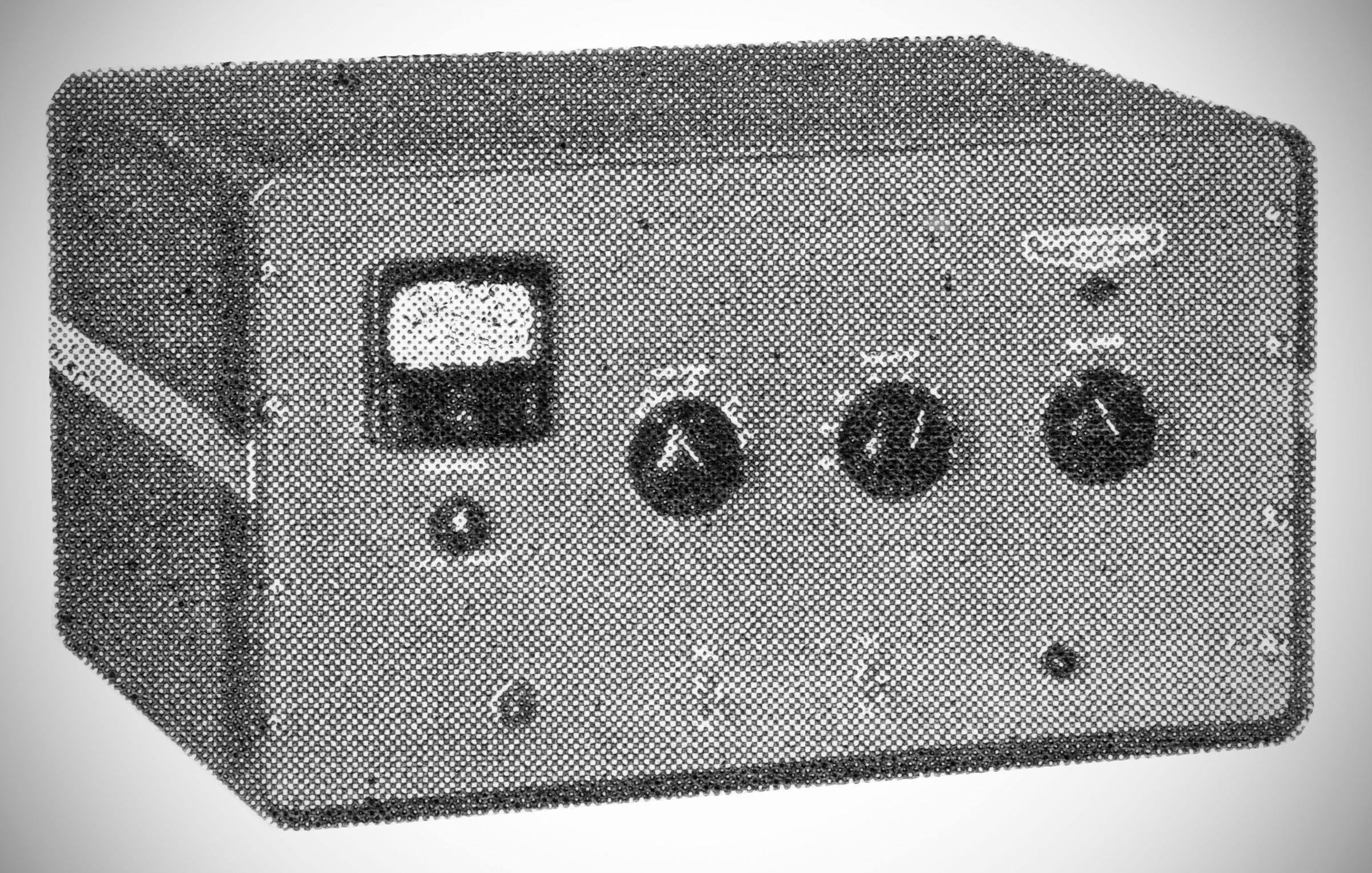
The Gonset GSB-101 (Model 3262) is a grounded-grid linear amplifier physically styled and sized to serve as a matching companion unit for the Gonset GSB-100 transmitter/exciter.
Features
Self-Contained Power Supplies: The plate power and internal operating bias supplies are integrated into the same cabinet, removing the need for external power cabling. It develops roughly –4 volts of operating grid bias natively.
Single-Knob Pi-Network Tuning: The output matching network uses a single band-switch control that simultaneously adjusts both the final tank inductance and a sequence of parallel capacitors, offering unified band selection and coarse loading.
Quiet Antenna T-R Relay: It features an internal DPDT antenna change-over relay operated on filtered DC (converted from the 115 VAC keying line) to ensure quiet actuation. It includes rear connectors for the main antenna and a receiver antenna lead.
Optional Cut-Off Bias: A rear terminal strip allows the introduction of an external 100 volt bias to completely cut off the 811A tubes during standby/receive periods, suppressing residual rectifier "hash" noise.
Specifications
– Power Input:
1200 watts PEP SSB
900 watts CW
400 watts AM
– Power Output to Antenna:
800 watts PEP SSB
700 watts CW
160 watts AM
– Gain & Drive Requirements: Provides approximately 10 db of gain and can be driven by exciters capable of delivering roughly 75 watts of RF drive into a 50-ohm load.
– Impedance: 50 ohms nominal for both input and output (supporting an SWR less than 3:1).
Tube Complement
The amplifier utilizes a total of six vacuum tubes:
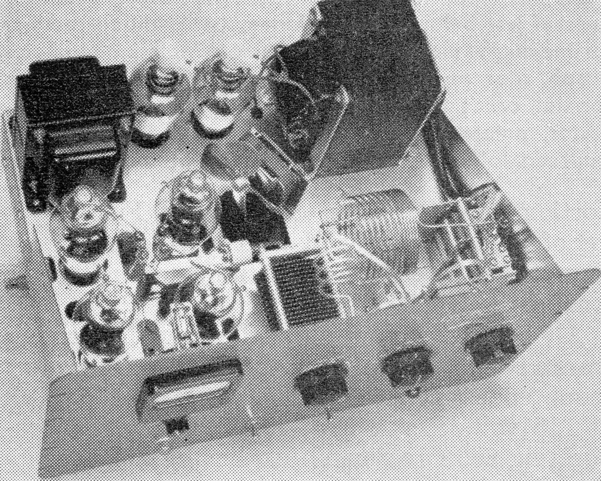
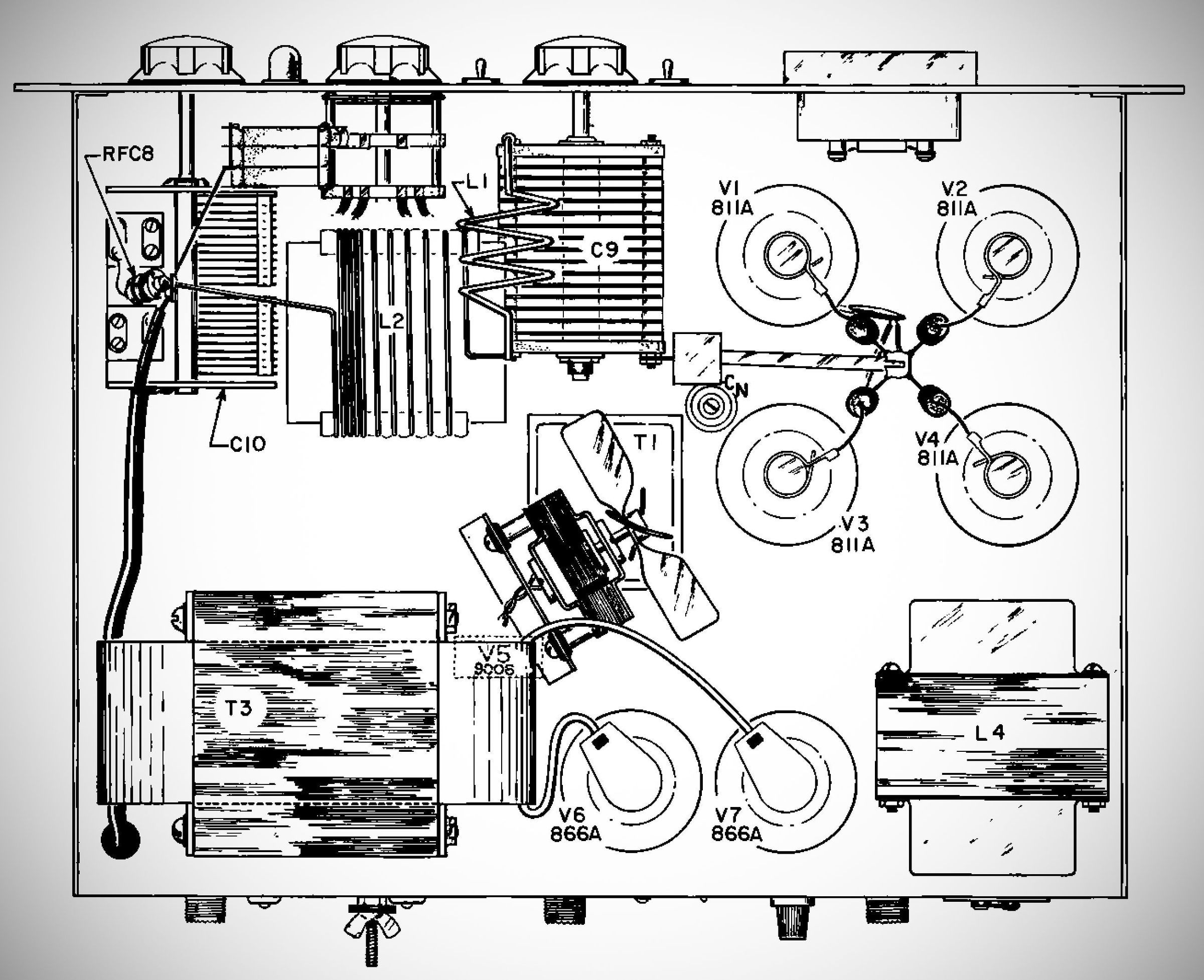
– (4) 811A triodes, connected in parallel in the grounded-grid amplifier stage.
– (2) 866A mercury-vapor rectifier tubes in the high-voltage power supply line.
(Note: A single 9006 diode (V5) is also used for the front-panel relative RF output indicator circuit).
Power Requirements: 110–125 VAC, 60 Hz, 1500 watts (Max)
References
Review: QST, Aug 1960, p. 45.