Note
QST, Dec 1963, p. 107.
QST, Mar 1964, p. 1.
QST, Mar 1965 p. 103.
QST, Apr 1966 p. 168. ("limited quantities," probably NOS)
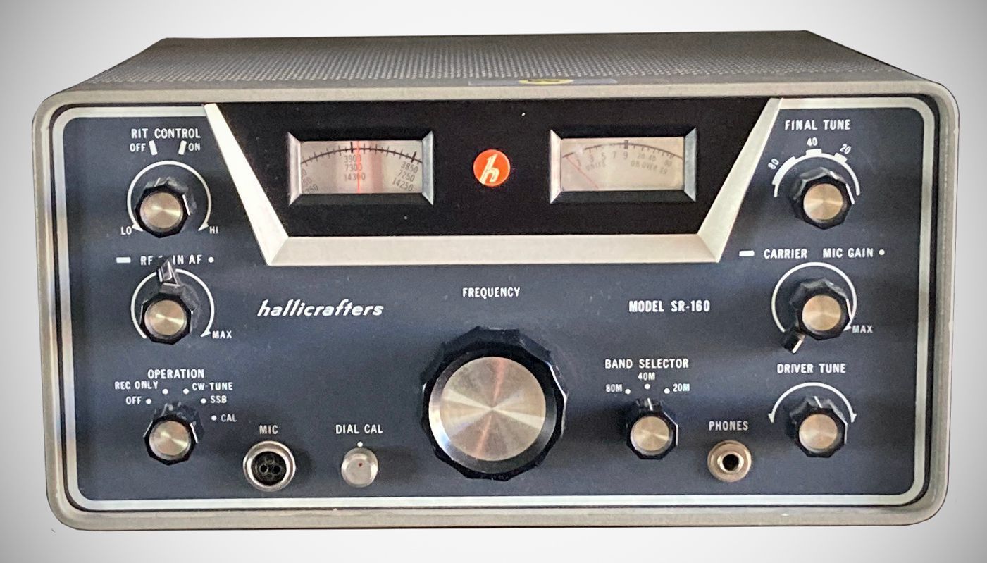
The SR-160 was a tri-band transceiver covering 80, 40, and 20 meters. It used a pair of 12DQ6B finals. Power input was 150 watts PEP on SSB and 125 watts on CW.. It is a versatile piece of equipment that can be operated as either a fixed base station or as mobile equipment. The unit utilizes 17 tubes and a single conversion receiver.
In 1965 the SR-160 was developed into the SR-500.
Key Features
– Receiver Incremental Tuning (RIT): Allows the operator to tune the receiver approximately 3 KC on either side of the transmitter frequency without affecting the transmitter frequency itself.
– Amplified Automatic Audio Level Control (AALC): Functions during transmission to prevent signal "splatter" by providing roughly 15 DB of compression when final amplifier "flat-topping" occurs.
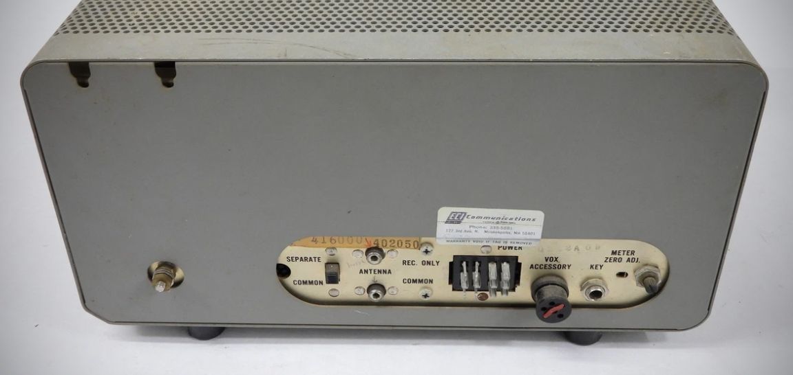
– Operating Modes: Supports manual SSB (push-to-talk) and manual CW operation. It also has provisions for voice-controlled SSB operation (VOX) using an optional accessory.
– VFO and Calibration: Features a stable, accurately calibrated VFO and a built-in 100-KC crystal calibrator circuit (though the crystal and tube for the calibrator are not supplied with the standard unit).
– Filtering and Detection: Includes a crystal-lattice filter and a product detector for improved performance.
– Metering: Equipped with an S-meter/RF output level indicator.
Specifications
– Frequency coverage:
80M (3500-4000 KC)
40M (6900-7400 KC)
20M (13900-14400 KC)
– Power Input: SSB: 150 watts PEP max; CW: 125 watts max
– Stability: Within 300 Hz after warmup
– Antenna Input/Output: 50 ohms
– Transmitter Output Impedance: Fixed, 50-ohm pi-network
– IF: 5200 kHz
– Receiver Sensitivity: 1 uV for a 20-DB signal-to-noise ratio
– Receiver Audio Output: 2 watts into 3.2 ohms
– Carrier/Sideband Suppression: 50 DB
– Calibration Accuracy: Less than 2 KC between 100-KC points after indexing
Tubes
V1 (12AW6): Receiver RF Amplifier
V2 (12BE6): Receiver Mixer
V3 (12BZ6): First IF Amplifier
V4 (6EA8): Receiver Second IF Amplifier and Meter Amplifier
V5 (12AX7A/ECC83): Product Detector and First Audio Amplifier
V6 (6AQ5A): Receiver Audio Output
V7 (12AU6): 100-KC Calibrator Oscillator (Note: This tube was not supplied with the standard unit)
V8 (12AT7): Carrier Oscillator/BFO and Third Microphone Amplifier
V9 (12AT7): First and Second Microphone Amplifier
V10 (6AM8A): AVC/AALC Amplifier-Detector
V11 (12BE6): Heterodyne Oscillator and Mixer (40M)
V12 (OA2): Voltage Regulator
V13 (12BE6): Transmitter Mixer
V14 (12BY7A): Transmitter Driver
V15 (12DQ6B): Transmitter Power Amplifier
V16 (12DQ6B): Transmitter Power Amplifier
V17 (6EA8): VFO and Cathode Follower
Available Accessories
– PS-150-120: 117-volt AC power supply with a built-in 4"x6" speaker for fixed-station use.
– PS-150-12: 12-volt DC power supply for mobile use.
– MR-160: Mobile installation kit including mounting brackets and cabling.
– HA-16: VOX control unit for voice-controlled operation.
References
Review. 73, Apr 1964, p. 24.
Converting the SR-160 to an SR-500. Ham Radio, Feb 1970, p. 66.