Note
QST, Aug 1957, p. 1.
QST, May 1959, p. 107. (some technical notes)
QST, Sep 1959, p. 101. ("where is the FPM-200?")
QST, Mar 1960, p. 87. (Still not quite there.)
QST, Apr 1960, p. 87. (notes on)
QST, Oct 1961, p. 157. (listed for sale with accessories)
Allied Radio catalog 1962 (copyright 1961), p. 273.
Allied Radio catalog 1963 (copyright 1962), p. 280.
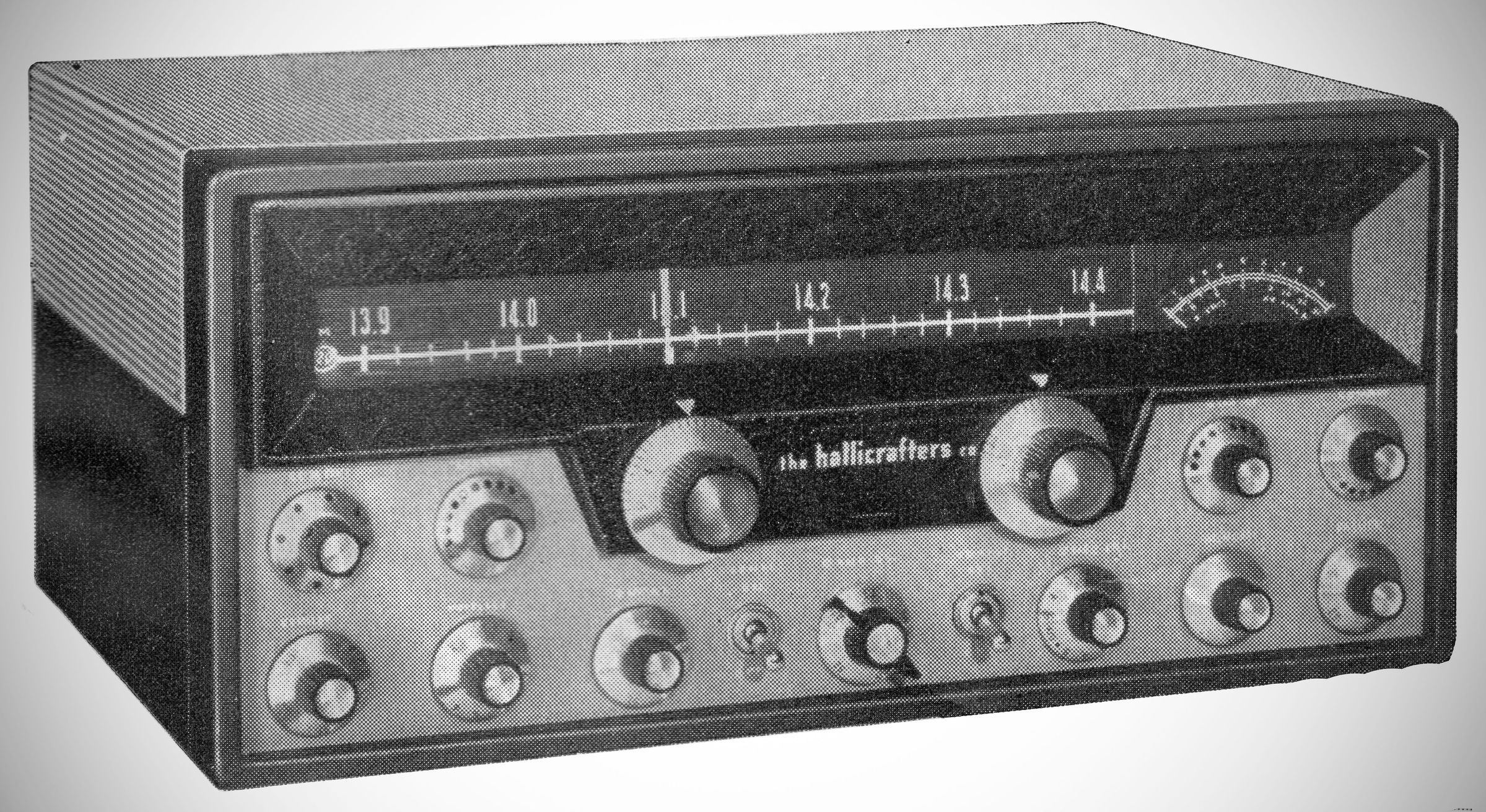
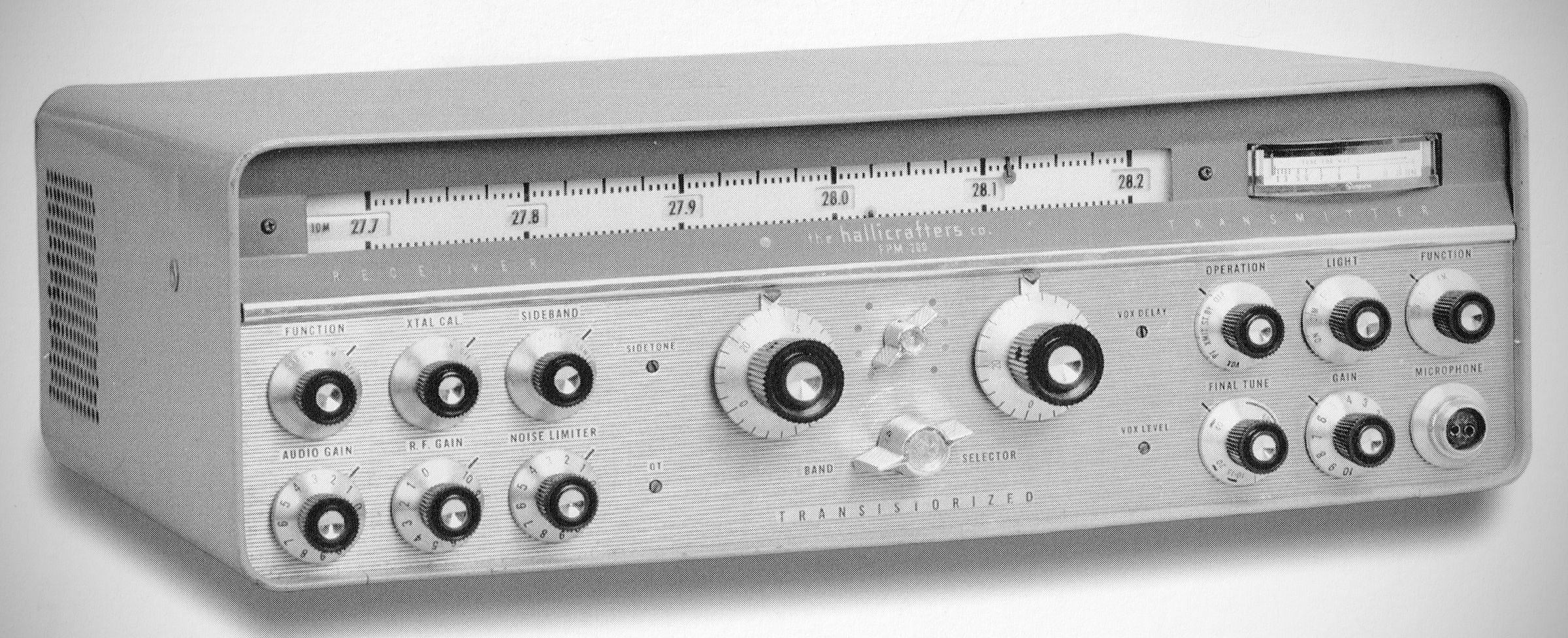
Hallicrafters announced an astonishing new radio in the summer of 1957. The FPM-200 was a full-featured transmitter/receiver for the 80-10 meter amateur bands on CW, AM, and SSB.
The receiver section and low-level transmitter stages were solid-state. Its 6146 finals, their 12BY7 driver, and a pair of 0B2 voltage regulators were the only tubes used. The FPM-200's dual PTOs provided linear tuning with calibration in 1 kHz increments. A front-panel switch enabled transceive operation with either PTO, as well as separate transmit and receive functions using both of them.
The radio ran directly off 12 VDC. An internal multivibrator supply furnished high voltage for the tubes.
From the outset, Hallicrafters had trouble getting the FPM-200 to market. In fact, there is disagreement about whether it ever became a real production item at all. Estimates range from a total of about 50 to nearly 200.
In QST, Hallicrafters last talked about the FPM-200 in April 1960. There was no subsequent discussion of the unit. And in QST, the FPM-200 appears to have been advertised for sale only once (and without any real fanfare), in a World Radio Labs (WRL) ad in the October 1961 issue. Hallicrafters did not mention the unit in any of its own advertising. The rig did appear in both the 1962 (copyright 1961) and 1963 (copyright 1962) Allied Rado catalogs.
When it finally appeared in 1961, the FPM-200's price tag of $1795 was worth almost $20,000 in 2025 currency.
General Description
The Hallicrafters Model FPM-200 is a complete, compact, self-contained radio station of advanced design. The versatility of the model FPM-200 permits it to be operated as fixed, portable, or mobile equipment.
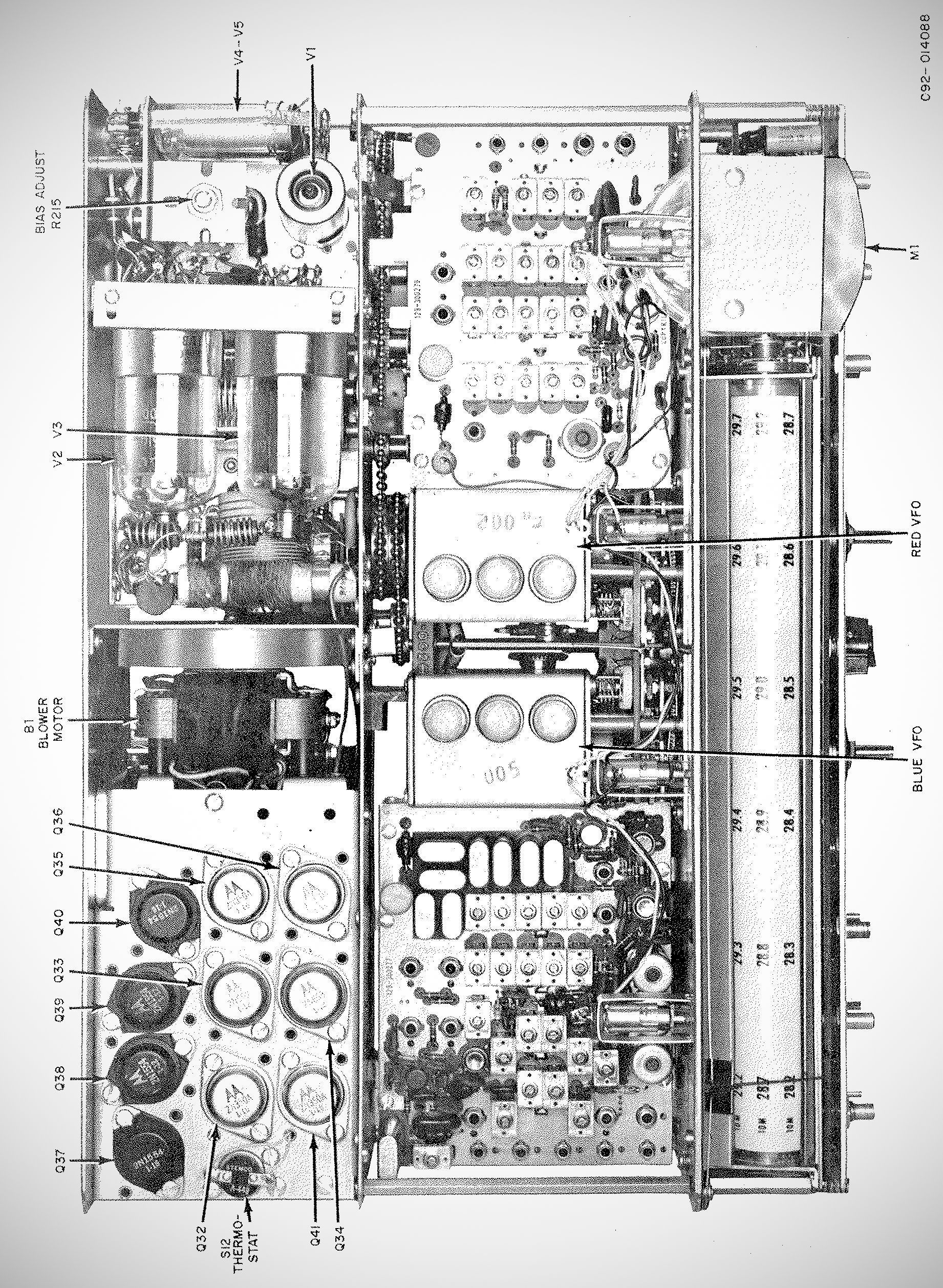
The unit is of the hybrid type using a combination of 41 transistors, three vacuum tubes, and voltage regulator tubes. The power supply, the receiver circuits, and the low-level transmitter stages are completely transistorized. The high power stages of the transmitter use three vacuum tubes to develop the required power for transmitting and two gas tubes to regulate the screen voltage for the final amplifier stage.
The FPM-200 provides for AM, CW, and SSB operation on the 80, 40, 20, 15, and 10 meter bands. An additional range is provided in the receiver for the reception of WWV on 10 MHz. Each tuning range is 500 kHz, readable directly in kilohertz.
Two VFOs are provided with selection to permit the equipment to operate as an independent transmitter and receiver on different frequencies within a given band, or to operate as a transceiver on one frequency--both functions being controlled by one oscillator.
A built-in, 100-KC crystal oscillator permits a front-panel adjustment for calibration of the VFO kilocycle dials.
Other features of this unit include an "S" meter which indicates receiver signal strength, as well as transmitter RF output level; modular construction (glass epoxy circuit boards); upper and lower crystal lattice filters (2.325 MHz) for transmitting and receiving; adjustable noise limiter; fast AGC for SSB operation; single control transmitter tune-up; blower for air circulation around tubes and internal power supply; and keyed tone through SSB system for CW transmission.
Specifications
– Frequency Coverage:
WWV: 9.7 to 10.2
80m: 3.5 to 4.0
40m : 6.8 to 7.3
20m: 14.0 to 14.5
15m: 21.0 to 21.5
10m: 27.7 to 28.2
10m: 28.2 to 28.7
10m: 28.7 to 29.2
10m: 29.2 to 29.7
– Filter and 2nd IF: 2.325 MHz
– VFO range: 8.250 MC to 8.750 MHz
– Stability: 0.009% maximum
– Dial Calibration: Linear 1 kHz
– Calibration Accuracy: ±1000 Hz after indexing to internal 100 kHz standard
– Sensitivity AM: Better than 3 microvolts for a 10-DB S+N/N
– Sensitivity SSB: Better than 1 microvolt for 10 DB S+N/N
– Selectivity: 2.5 kHz at 6 DB; 6 kHz at 60 DB
– Audio Power Output: 3 watts
– Output Impedance: 3.2 ohms and 500 ohms
– Output Power:
SSB PEP: 70 watts to 100 watts
CW: 60 watts to 90 watts
AM carrier: 15 watts to 20 watts
– Carrier Suppression: -50 DB
– Unwanted Sideband Suppression: -50 DB
– Hum and Noise: -40 DB
– Distortion Products: -30 DB
– Audio Input (Microphone): 0.004 volts RMS minimum
Power Consumption
Standby: 30.0 watts
AM 100% Modulation: 216 watts
SSB, No Signal: 132 watts
SSB, Maximum Output: 216 watts
CW, Maximum Output: 288 watts
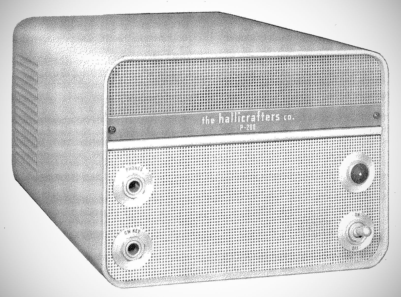
AC Power Supply/Speaker:| 7" wide, 5 " high, 11" deep, 27.5 pounds
DC Power Consumption:
No Signal: 10 watts
Maximum Audio Signal: 23 watts
Transistors: 41
Diodes: 49 including 14 power rectifiers
Tubes: (1) 12BY7A, (2) 6146, (2) 0B2
References
A sneak peak. CQ, Oct 1959, p. 38.