Note
QST, Feb 1957, p. 147.
QST, Apr 1957, p. 117. (lots of specs)
QST, Oct 1957, p. 1.
QST, May 1958, p. 1. (new 5 MHz quartz filter??)
Allied Radio catalog 1958 (copyright 1957), p. 265.
QST, Jan 1959, p. 2. (HT-32A, $695.00)
Allied Radio catalog 1962 (copyright 1961), p. 273. (HT-32B)
QST, Jan 1963, p. 1. (HT-32B)
Allied Radio catalog 1963 (copyright 1962), p. 280.
Allied Radio catalog 1964 (copyright 1963), p. 218.
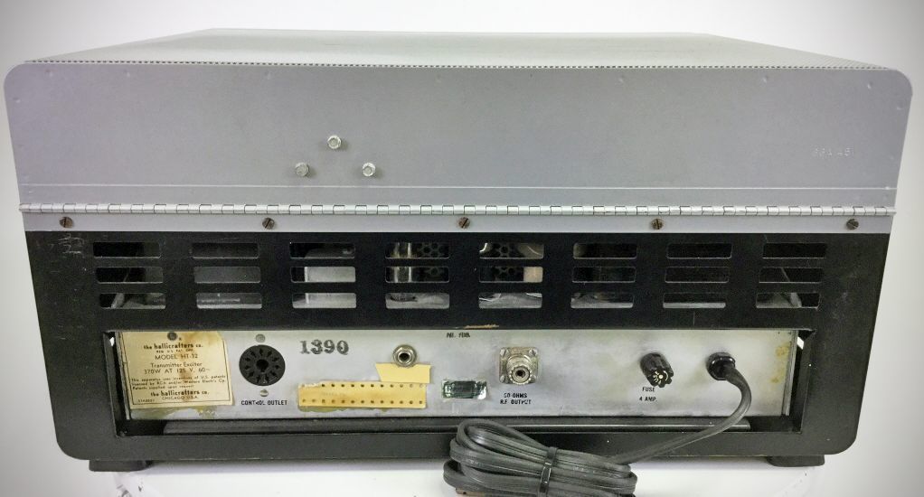
The HT-32 used a bridged-tee balanced modulator and a 4.95 MHz crystal filter to generate SSB. It also transmitted AM and CW. Power output from the 6146 finals was 70-100 watts on SSB and CW, 17-25 watts on AM. The HT-32 covered 80 through 10 meters using a linear, capacitor-tuned VFO.
The tuning knob's skirt was calibrated in kHz. The transmitter had VOX, but no provision for PTT operation. There was no load control for the pi-net output circuit. It was set for 50 ohms on each band using fixed capacitors
Its styling matched that of the SX-115 receiver.
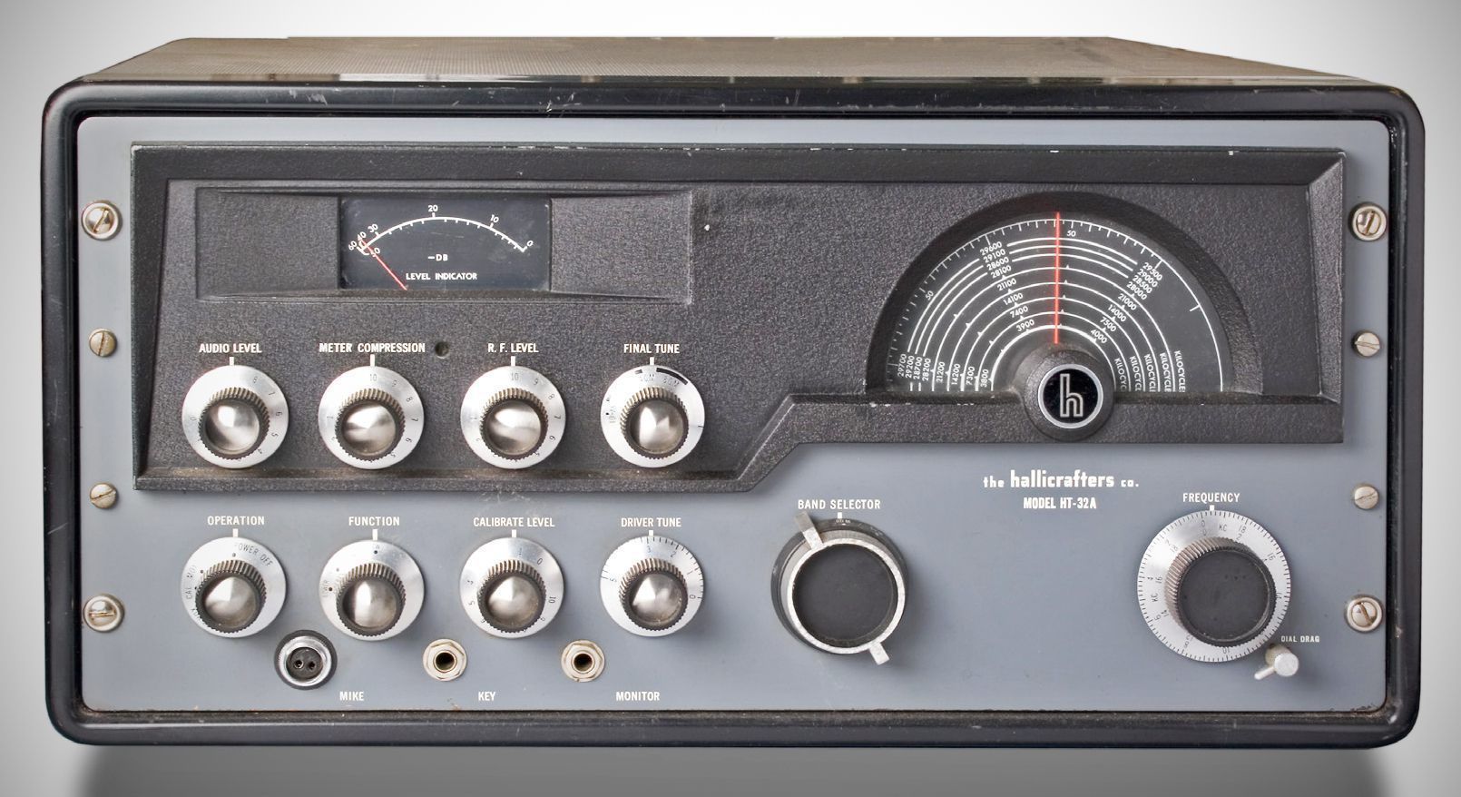
The HT-32A added push-to-talk operation, as well as provision for phone patching and RTTY, to the HT-32’s specs. There is little to distinguish them cosmetically.
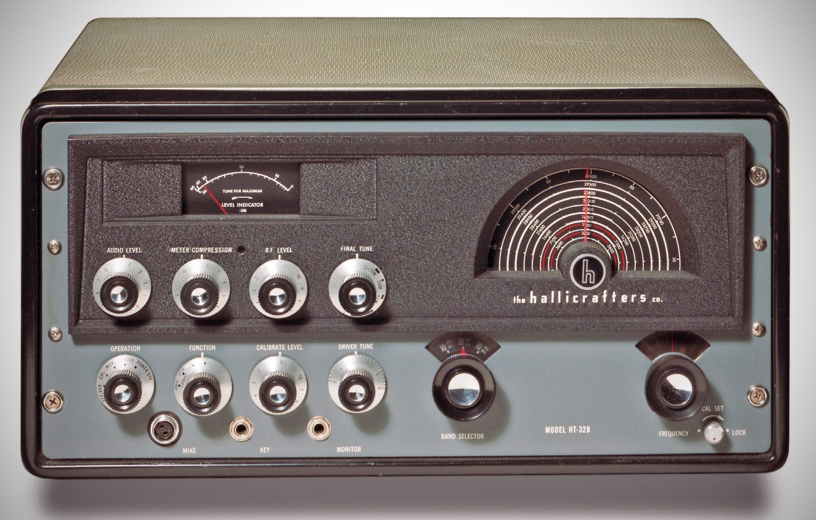
The HT-32B was the final model of the HT-32 series. Changes from the HT-32A were largely cosmetic, with the styling more closely matching the SX-115 receiver. In addition to SSB and CW, it transmitted AM with both sidebands.
Here are the technical specifications from page 14 of the manual, converted to standard sentence casing:
Specifications
– Power output:
SSB (PEP): 70–100 watts
CW: 70–100 watts
AM (Carrier): 17–25 watts
– Audio input: 0.004V rms minimum
– Stability: 0.009% maximum
– Hum and noise output: At least 40 dB below carrier
– Unwanted beat output: At least 55 dB below carrier
– Frequency coverage: 80, 40, 20, 15, and 10 meter bands
– Frequency selection: Self-contained VFO
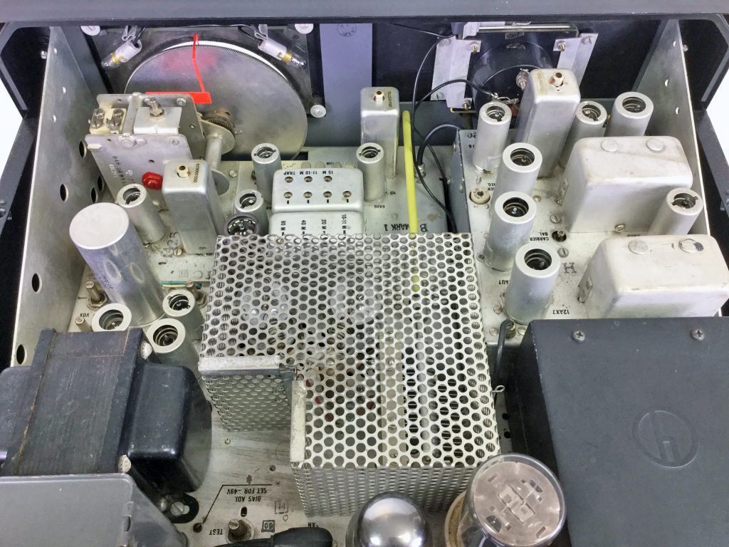
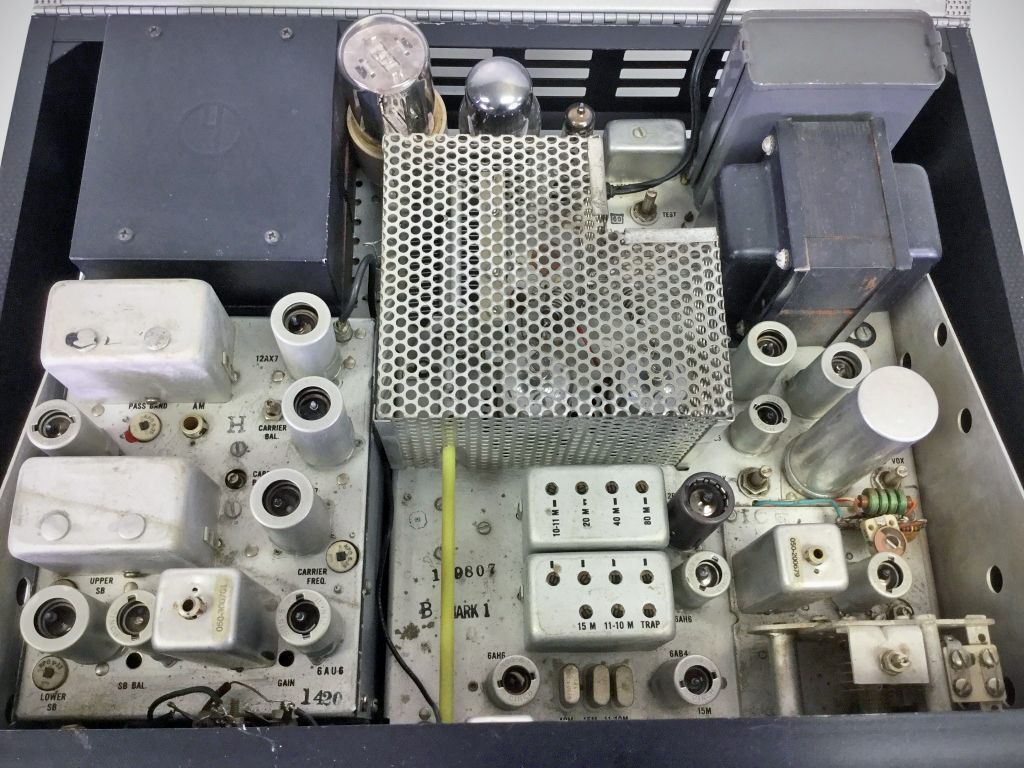
Tube Complement (HT-32A) (20 total)
– 6BA6 (Audio Amplifier)
– 12AX7 (Audio Amplifier and Driver)
– 12AT7 (4.95 MHz Crystal Oscillator and Modulator Driver)
– 6AL5/5726 (Balanced Modulator)
– 6AH6 (4.95 MHz IF Amplifier)
– 6AH6 (First Mixer)
– 6AH6 (Second Mixer)
– 6AH6 (Driver)
– 6146 (RF Power Amplifier - Final)
– 6146 (RF Power Amplifier - Final)
– 12BY7A (RF Driver / Pre-Driver)
– 12AU7 (Variable Frequency Oscillator - VFO)
– 6CB6 (VFO Buffer)
– 6AB4 (Heterodyne Crystal Oscillator)
– 12AT7 (VOX Amplifier)
– 12AU7 (Anti-Trip Amplifier and VOX Rectifier)
– 6AU6 (Calibrator / Sideband Oscillator)
– 0A2 (Voltage Regulator)
– 5R4GY (High-Voltage Rectifier)
– 5V4GA (Low-Voltage Rectifier)
Power Requirements: 105–125 VAC, 50/60 Hz
References
PTT or remote send-receive. CQ, Nov 1959, p. 74.
Add a frequency shift keyer. CQ, Apr 1964, p. 34.