Note
QST, Nov 1960, p. 1.
QST, Dec 1960, p. 189. (specs)
QST, Jan 1964, p. 173.
QST, Mar 1965 p. 103.
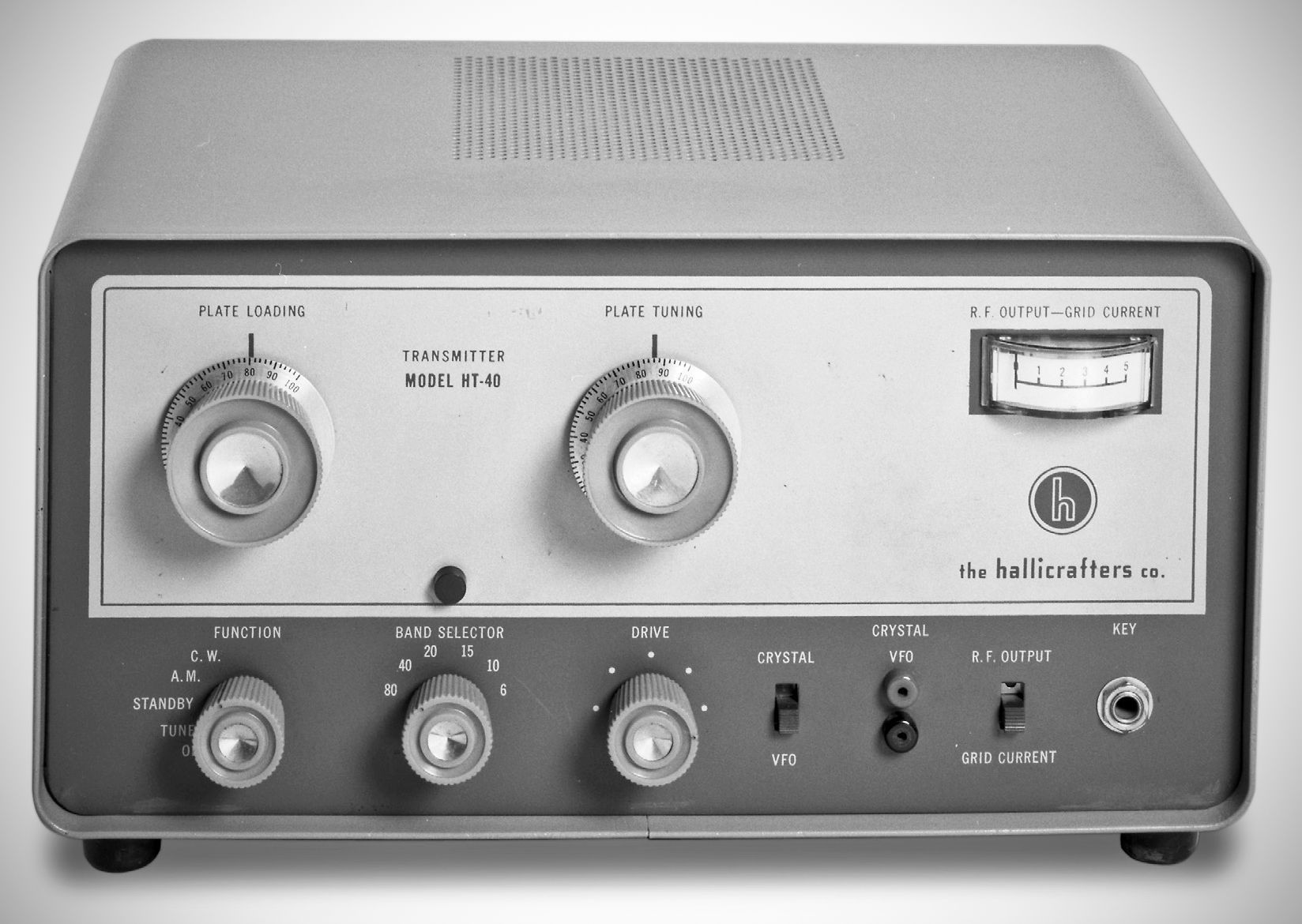
The HT-40 transmitter and its companion receiver, the SX-140, were available both as “Halli-Kits” and wired and tested. The crystal-controlled, 75 watt rig featured band-switching coverage of 80–6 meters and worked AM phone as well as CW. The final amplifier was a 6DQ5.
In an effort to make it easier for the novice to tune, instead of adjusting the final amplifier for a traditional plate current dip, the HT-40 features a front-panel meter driven by a diode rectifier connected to the output coupler. The operator tunes the final for peak output power on the meter. A toggle switch allows the meter to alternate between reading relative RF output power (calibrated at roughly 10 watts per scale division) and final grid current (up to 5 mA). CW operation utilizes cathode keying across all RF stages.
Specifications
– Mode: AM, CW
– Frequency Selection: Crystal controlled or external VFO
– Frequency Coverage: 80, 40, 20, 15, 10, and 6 meter amateur bands
80 m: 3.5 to 4.0 MHz (crystal/VFO range 3500 to 4000 kHz)
40 m: 7.0 to 7.3 MHz (crystal/VFO range 7000 to 7300 kHz)
20 m: 14.0 to 14.35 MHz (crystal/VFO range 7000 to 7175 kHz)
15 m: 21.0 to 21.45 MHz (crystal/VFO range 7000 to 7150 kHz)
10 m: 28.0 to 29.7 MHz (crystal/VFO range 7000 to 7425 kHz)
6 m: 50.0 to 54.0 MHz (crystal/VFO range 8333 to 9000 kHz)
– Power Input:
AM: 75 watts peak power
CW: 75 watts maximum
– Power Output:
CW: Approximately 43 watts
AM: 39 watts peak on AM
(slightly reduced output on 6 meters).
– Antenna Output: Pi-network coupling into 50–75 ohm unbalanced coaxial lines.
– Audio Input: 0.004 V minimum at input to microphone jack
– Distortion: 8% at 75% modulation
– Hum and Noise Output: 40 dB or more below maximum output
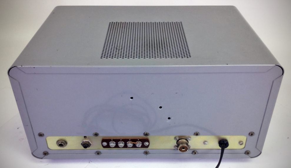
– CW Keying: Panel-mounted key jack accepting standard 2-connector 1/4-inch plug (also equipped with rear accessory terminal strip connections)
– Microphone Input: Rear chassis-mounted microphone receptacle (Amphenol 75-MC1F connector)
Tube LIneup
– 6CX8
– 6DQ5
– 12AX7
– 6DE7
– two silicon rectifiers
Power Supply: Transformer-driven using a full-wave silicon diode voltage doubler to reduce internal heat, followed by a pi-type filter choke network.
Power Requirements: 105–125 VAC, 60 Hz, 175 watts
References
Review. Popular Electronics, Sep 1961, p. 75.