Note
QST, Nov 1962, inside front cover.
QST, Jan 1964, p. 167.
QST, May 1964, p. 1.
QST, Mar 1965 p. 103.
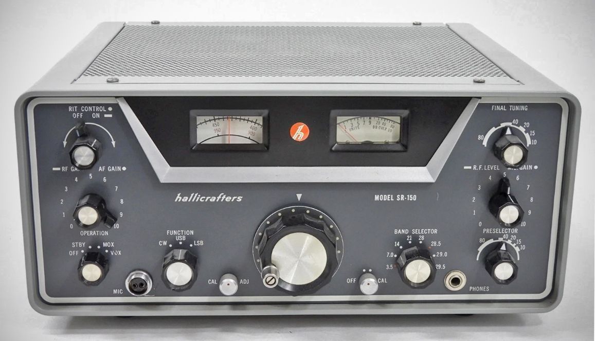
Hallicrafters' SR-150 transceiver offered coverage of 80-10 meters in eight 500 kHz bands. Six of the ranges were used for 80 through 15, plus one 500 kHz segment of 10 meters. The two additional ranges could be used to complete coverage on 10 or for non-amateur operation such as MARS. The SR-150 had RIT and used a crystal filter in its 1650 kHz IF. The circuit contained 11 solid-state devices and 19 tubes, including a 12BY7 driver and 12DQ6B finals. Power input was 150 watts SSB and 125 watts CW.
Features
– Receiver Incremental Tuning (RIT): This control enables the operator to unlock the receiver frequency and tune approximately two KC on either side of the transmitter frequency.
– Automatic Audio Level Control (AALC): This amplified circuitry functions in the transmit mode to prevent splatter caused by severe flat-topping of the final amplifier.
– Stable VFO and Calibrator: It features a stable, accurately calibrated VFO and a built-in 100-KC crystal calibrator.
– Versatile Operating Modes: Supports upper and lower sideband, PTT, VOX, Manual CW, and break-in CW operation.
– Advanced Filtering and Detection: Equipped with a crystal-lattice filter and a product detector.
– Signal Indicators: Includes a combination S-meter and RF output level indicator.
Specifications
General
– Frequency Coverage: Full coverage for 80, 40, 20, 15, and one segment of the 10-meter band, with provisions available for the remaining three segments of the 10-meter band.
– Ambient Temperature Range: Minus 20° to plus 50°C.
– Dial Calibration: 5-KC increments.
Transmitter
– Power Input: 150 watts PEP MAX for SSB, and 125 watts MAX for CW.
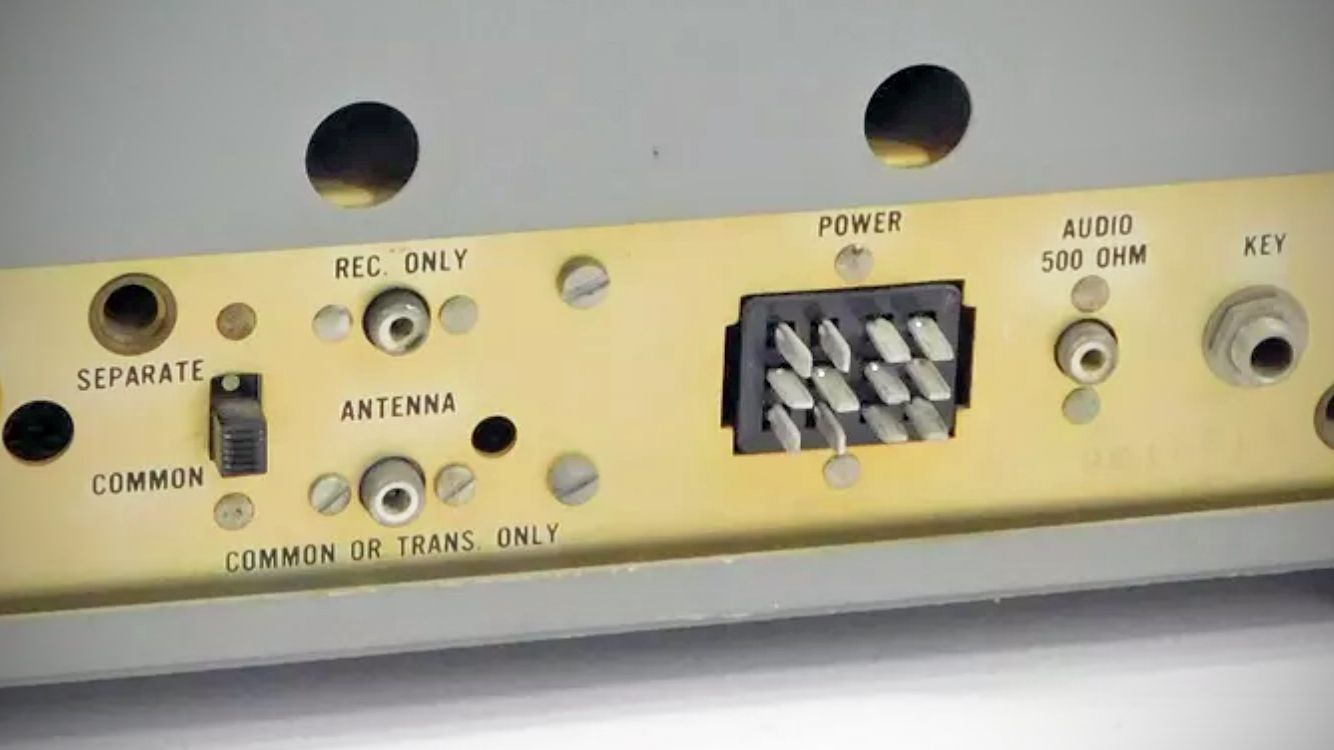
– Output Impedance: Fixed, 50-ohm pi-network.
– Output Tubes: Two 12DQ6B tubes in parallel.
– Suppression: Carrier and unwanted sideband suppression is rated at 50 DB.
– Distortion Products: 30 DB.
– Audio Response: 600 CPS to 2800 CPS at 3 DB.
– Microphone Input: High impedance.
Receiver
– Sensitivity: 1 microvolt for a 20-DB signal-to-noise ratio.
– Audio Output: 2 watts.
– Output Impedance: 3.2 ohms and 500 ohms.
– Antenna Input: 50 ohms.
– IF: Dual Conversion featuring a variable First IF of 6.0 MC to 6.5 MC and a Second IF of 1650 KC utilizing a crystal-lattice filter.
– VFO Stability: Less than 300 Hz after warmup.
Tubes
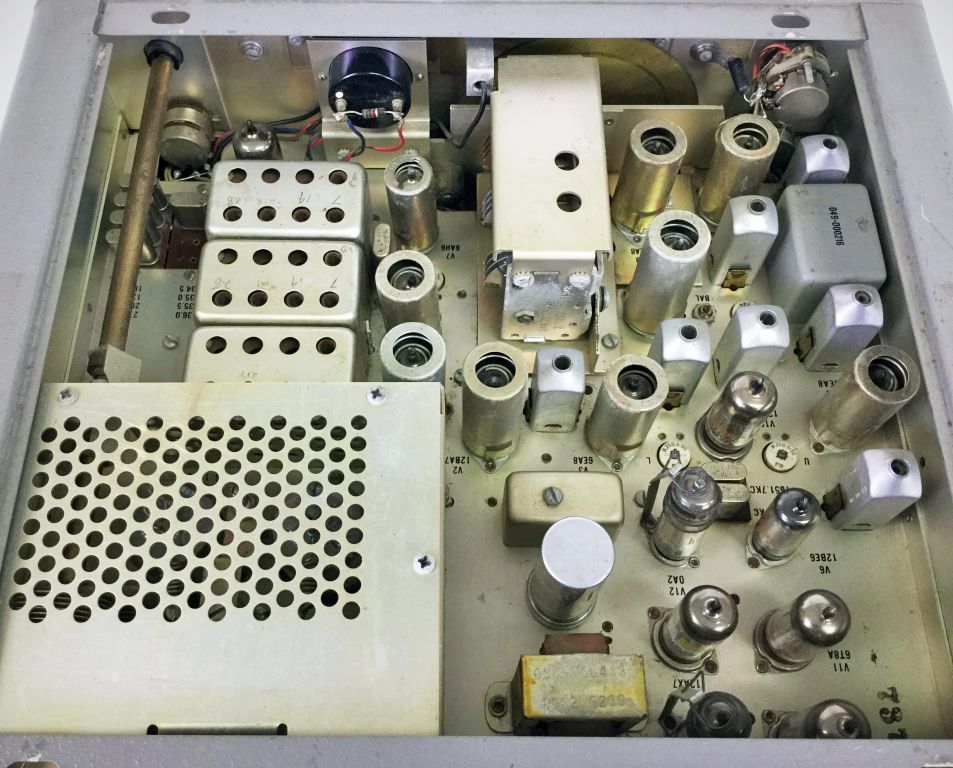
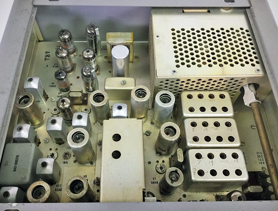
V1 (6AZ8): Receiver RF Amplifier and Calibrate Oscillator
V2 (12BA7): Receiver and Transmitter First Mixer
V3 (6EA8): 6.0-MC to 6.5-MC IF Amplifier and Audio Cathode Follower
V4 (12BA7): Receiver Second Mixer
V5 (6EA8): Receiver Second 1650-KC IF Amplifier and AALC Amplifier
V6 (12BE6): Product Detector
V7 (6AH6): Transmitter Second Mixer
V8 (12AT7): Heterodyne Oscillator and Cathode Follower
V9 (6EA8): VFO and Cathode Follower
V10 (12AT7): Carrier Oscillator/BFO
V11 (6T8A): Receiver First Audio, AGC Detector, VOX Diode, and QT Diode
V12 (OA2): Voltage Regulator
V13 (6AQ5A): Receiver Audio Output
V14 (12DQ6B / 12GW6): Power Amplifier
V15 (12DQ6B / 12GW6): Power Amplifier
V16 (12BY7A): Transmitter Driver
V17 (6EA8): Receiver and Transmitter 1650-KC IF Amplifier and Meter Amplifier
V18 (12AX7): First and Second Microphone Amplifier
V19 (12AT7): VOX Amplifier and VOX Relay Amplifier
Review: QST, Jun 1963, p. 58.