Note
QST, Dec 1965, p. 1.
QST, Aug 1966, p. 1.
QST, Mar 1967, inside front cover.
QST, Feb 1967, inside front cover. specs.
QST, Apr 1968, p. 1.
QST, Jan 1970, inside front cover.
QST, Feb 1971, p. 1.
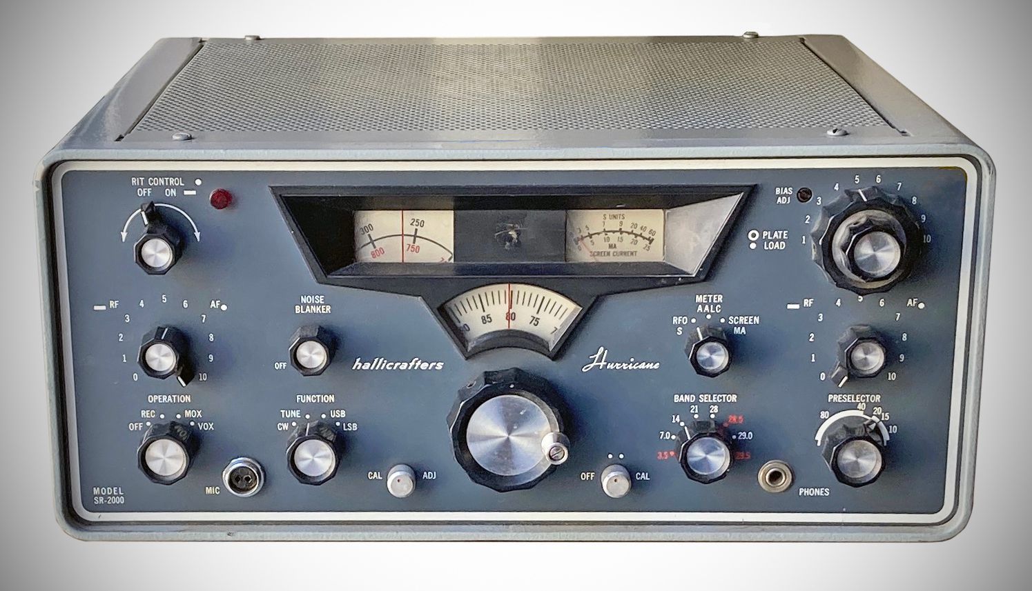
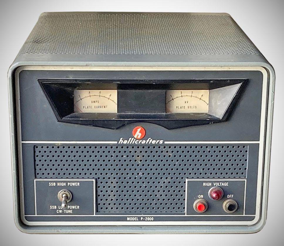
The SR-2000 Hurricane was Hallicrafters' legal-limit desktop station. The 2000 watt PEP SSB and 900 watt CW transceiver covered 80-10 meters, tuning the bands in 500 kHz ranges. Its double-conversion receiver incorporated RIT and shared a 1650 kHz crystal lattice filter with the transmitter. A pair of 8122s served as the transmitter's final amplifier. The P-2000 power supply was in a separate cabinet.
Features
– Receiver Incremental Tuning (RIT) control: approximately ±3 kHz
– Amplified Automatic Level Control (AALC): Functions in transmit mode to prevent splatter caused by severe flat-topping of the final amplifier signal by providing about 15 dB of compression at the onset of flat-topping.
– Noise blanker circuit: Operates ahead of the IF filter for effective noise-limiting action.
– Choice of VOX or PTT control for SSB operation, and a choice of manual or automatic break-in control for CW operation.
– Sideband selection: Upper and lower sideband operation with a common carrier frequency across all bands.
– Drive mechanism: Smooth gear-driven tuning mechanism with a 1-kilocycle readout display.
– VFO: Accurately calibrated VFO featuring excellent mechanical and temperature stability.
– Tuning rate: Constant tuning rate on all bands.
– IF Filter: Crystal lattice 1650 kHz filter with 6 poles for optimum selectivity and single sideband response.
– Product Detector: Features crystal-controlled beat frequency oscillator (BFO) injection for maximum stability.
– CW Monitoring: Keyed sidetone for monitoring CW transmissions.
– Signal Performance: Excellent modulation cross-overload characteristics.
– Final Amplifier Metering: Complete metering for the final amplifier tubes, including separate plate voltage, plate current, and screen current meters.
– Calibrator: Built-in 100 kHz crystal calibrator for exact dial calibration.
Specifications
– Tuning Ranges: 8 amateur band segments covering 3.5 to 4.0 MHz 80M, 7.0 to 7.5 MHz 40M, 14.0 to 14.5 MHz 20M, 21.0 to 21.5 MHz 15M, and 28.0 to 30.0 MHz in four 500 KHz steps 10M.
– Frequency Stability: Less than 250 Hz drift in the first hour after a 15-minute warm-up; less than 100 Hz per hour thereafter.
– Power Input:
SSB High Power: 2000 W PEP
SSB Low Power: 1000 W PEP
CW: 900 W maximum
– Power Output:
SSB High Power: 1000 W PEP
SSB Low Power: 500 W PEP
CW: 500 W
– Output Impedance: 50 ohms nominal adjustable 40 to 70 ohms non-reactive.
– Carrier Suppression: 60 dB below PEP output.
– Unwanted Sideband Rejection: 50 dB below desired output at 500 to 2500 Hz input.
– Sensitivity: 1 uV or less for a 20 dB signal-to-noise ratio.
– Audio Output: 1 Watt with less than 10% distortion.
– Dual Conversion System:
First IF: 6.0 MHz to 6.5 MHz
Second IF: 1650 KHz with a 6-pole crystal lattice filter
– RIT Frequency Range: 4 KHz minimum.
– Image & Spurious Rejection: Better than 50 dB.
Tube LIneup (20 total)
– 12DK6: Receiver RF Amplifier
– 7059: Receiver and Transmitter 1st Mixer
– 7059: IF Amplifier and AALC Amplifier
– 12AT7: 2nd Receiver Mixer and VFO Amplifier
– 7059: Noise Amplifier and Pulse Amplifier
– 6GX6: 1st 1650 KHz IF Amplifier and Blanker
– 7059: 2nd 1650 KHz IF Amplifier and Side Tone Amplifier
– 7059: AGC Amplifier and Meter Amplifier
– 12AT7: Product Detector and 1st Audio Amplifier
– 0A2: Voltage Regulator
– 7059: 2nd Transmitter Mixer and 100 KHz Crystal Oscillator
– 7059: Heterodyne Oscillator
– 12BA6: VFO
– 12AT7: BFO/Carrier Oscillator and 3rd Mic. Amplifier
– 6AQ5: Audio Output
– 8122: Transmitter Power Amplifier
– 8122: Transmitter Power Amplifier
– 12BY7A: Transmitter Driver
– 12AT7: 1st Mic. Amplifier and 2nd Mic. Amplifier
– 12AT7: VOX Amplifier and Relay Amplifier
Power Requirements
Input Voltage: 115 VAC, 2-wire OR 230 VAC, 3-wire, 60 Hz
Current & Circuit Rating: Under peak load, the equipment draws over 20 A on a 115 V line or over 10 A on a 230 V line. A dedicated 30 A circuit is recommended if operating from a 115 V source.
Power Consumption
Receive Mode: 175 W
Transmit Mode: 2300 W
Power Supply Output Capabilities & Transceiver Limits
– Final Amplifier Tube Ratings: Rated at 800 W plate dissipation.
– High-Voltage Plate Supply:
SSB High Power Mode: 2700 V DC (2000 W PEP input, 1000 W PEP output).
SSB Low Power / CW / Tune Mode: 1700 V DC (1000 W PEP input on SSB; 900 W maximum input on CW).
References
Brief description. Electronics World, May 1966, p. 90.