Note
CQ, Nov 1967, p. 73.
QST, Dec 1967, p. 178.
QST, Feb 1968, p. 1.
QST, Nov 1968, inside front cover.
QST, Jan 1969, p. 152.
QST, Apr 1971, p. 1. (SR-400A)
QST, Jan 1972, p. 1.
QST, Apr 1974, inside front cover.
QST, Jul 1974, p. 161. (on sale)
True dual receive when used with the HA-20.
Originally announced as the SR-540 (QST, May 1966, p. 1) in a preview ad saying "Watch for it next month." But the unit didn't actually appear until November 1966, about 18 months later, as the SR-400.
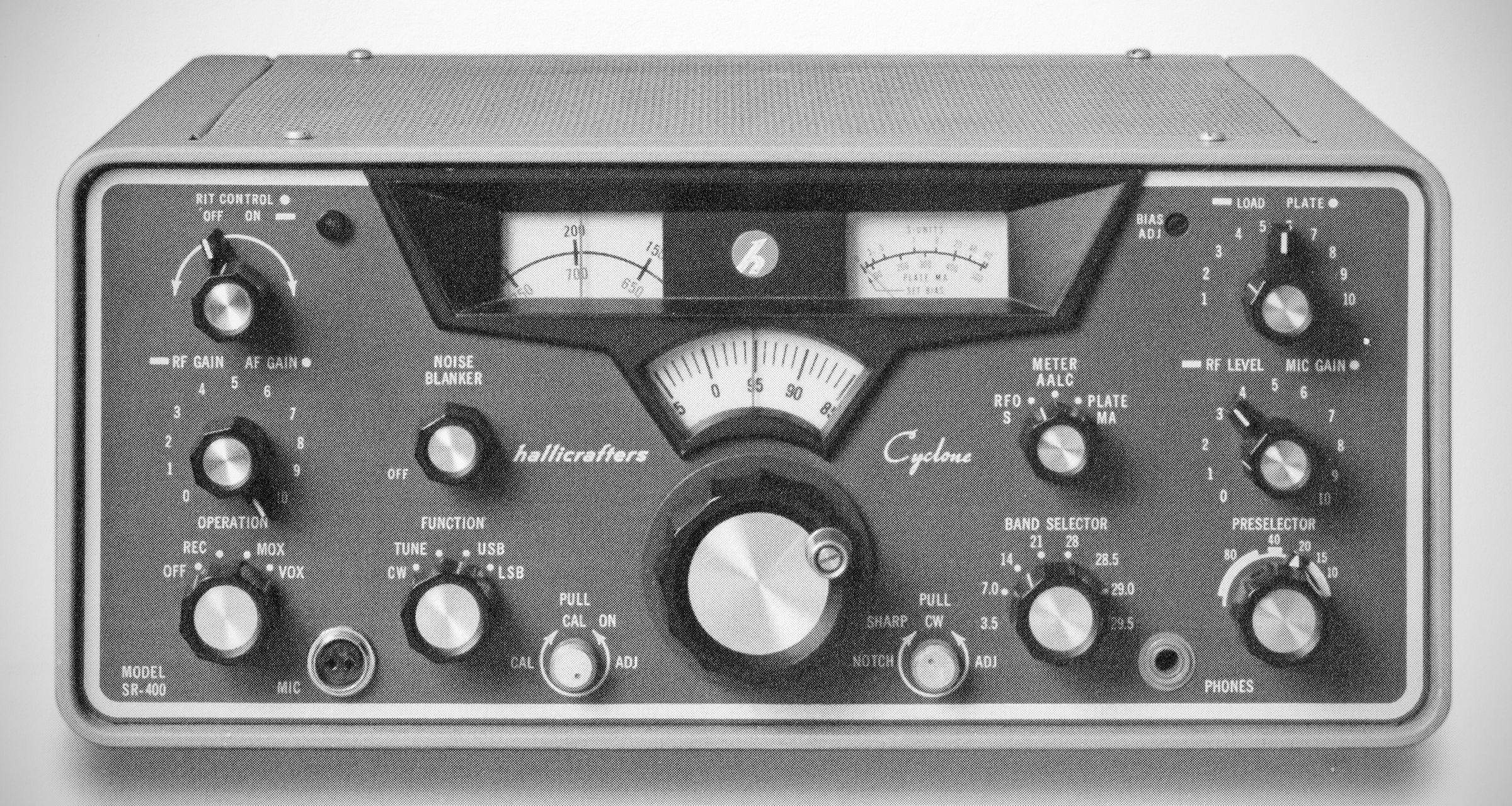
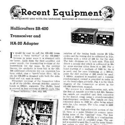
The Hallicrafters Model SR-400 Cyclone II is a vintage, high-performance amateur radio communications transceiver designed for fixed and mobile operation. It features double-conversion heterodyne architecture for both receiving and transmitting across the 80, 40, 20, 15, and 10-meter amateur bands.
The Hallicrafters SR-400 Cyclone and the SR-400 Cyclone II share the same core design, physical chassis, and target performance class (400W PEP SSB / 360W CW input utilizing a pair of 6HF5 final amplifier tubes). However, the Cyclone II represents a major mid-production circuit revision that resolved several operational, drive, and filtering quirks found in the original SR-400.
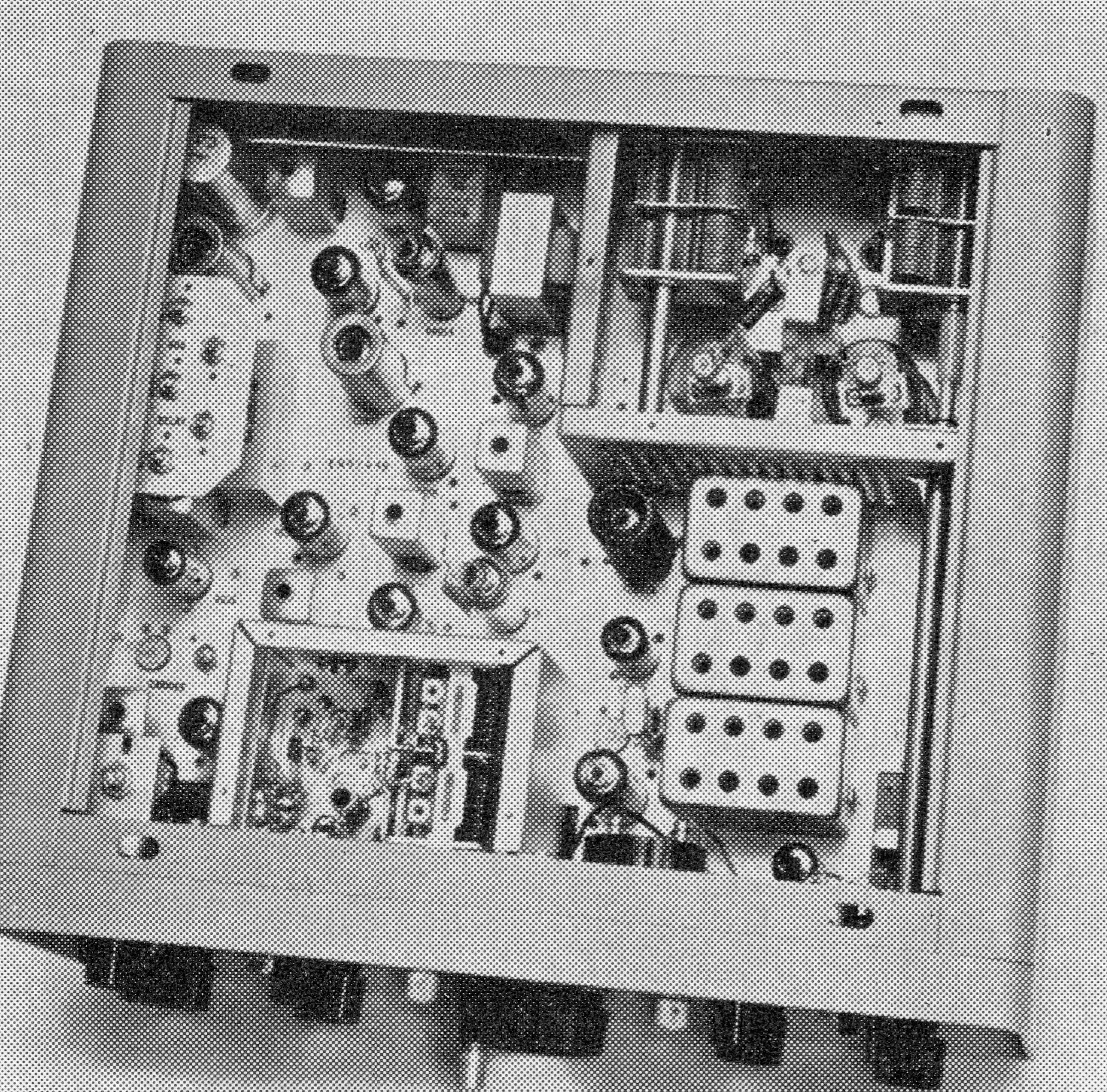
The most significant difference between the two models lies under the chassis:
– IF Filter & Audio Matching: The Cyclone II modified the resistor/filter network around the main crystal lattice filter and audio driver stages to improve overall receiver sensitivity and signal passband symmetry.
– RF Drive & CW Stability: The driver/mixer stages were re-worked to provide better drive level balance across all bands. Additional bypassing capacitors and chokes were introduced to curb spurious RF oscillations and transients.
– Notch & Noise Blanker Tweaks: The active notch and noise blanker circuitry underwent component updates for sharper suppression and improved performance near strong adjacent signals.
Features
– Receiver Incremental Tuning (RIT): Allows fine-tuning of the receiver frequency (±2 to 3 kHz) independently of the transmitter frequency.
– Amplified Automatic Level Control (AALC): Provides up to 15 dB of audio compression during transmission to prevent final amplifier flat-topping and signal splatter.
– Noise Blanker: Operates ahead of the IF filter system to eliminate high-impulse ignition and electrical interference.
– Rejection Notch Filter: Features an adjustable IF notch filter to attenuate interfering heterodynes or unwanted CW signals.
– Flexible Operating Modes: Full VOX (Voice-Operated Exchange) or PTT (Push-To-Talk) operation for SSB, plus manual or automatic break-in with a keyed sidetone monitor for CW.
– Metering: Multi-function meter on the front panel displays S-units, relative RF Output (RFO), AALC level, and final amplifier Plate Current (PLATE MA).
Here is the expanded technical specification sheet for the Hallicrafters SR-400 "Cyclone" HF transceiver:
Specifications
– Type: Double-conversion superheterodyne HF amateur transceiver.
– Frequency Coverage: 80, 40, 20, 15, and 10-meter amateur bands.
3.5 – 4.0 MHz (80m)
7.0 – 7.5 MHz (40m)
14.0 – 14.5 MHz (20m)
21.0 – 21.5 MHz (15m)
28.5 – 29.0 MHz (10m furnished; three extra crystal sockets available to cover 28.0 - 28.5 MHz, 29.0 - 29.5 MHz, and 29.5 - 30.0 MHz).
– Operating Modes: USB, LBS, and CW.
– Frequency Stability: Within 100 Hz overall drift after a brief warm-up period.
– Dial Accuracy & Readout:
Visual readout resolution to 1 kHz.
Dial accuracy better than 2 kHz across all bands.
– Power Input 400 Watts PEP (SSB), 360 Watts DC (CW)
– RF Power Output ~200 Watts (SSB / CW)
– Final Amplifier Tubes Pair of 6HF5 beam power pentodes
– Carrier Suppression Greater than 50 dB
– Unwanted Sideband Rejection Greater than 50 dB at 1 kHz audio
– Spurious Radiation Down more than 50 dB relative to peak output
– Unwanted Distortion Products Intermodulation products (3rd order) down at least 30 dB
– Antenna Output Impedance Nominal 50 Omega unbalanced, broad-banded Pi-network (matches VSWR up to 2:1)
– Microphone Input High-impedance crystal or dynamic microphone
– Transmit Control VOX or Push-to-Talk (SSB); manual or automatic break-in keying (CW)
– Sensitivity: Better than 0.5 muV input for a 10 dB Signal-plus-Noise to Noise ratio (S+N/N).
– Selectivity:
– SSB: 2.1 kHz at -6 dB; 3.8 kHz at -60 dB (utilizes a high-frequency crystal lattice filter).
– CW Filter: Sharp position provides 200 Hz bandwidth at -6 dB.
– IF Frequencies:
1st IF: Variable 1.650 - 2.150 MHz (Tunable IF).
2nd IF: 1650 kHz fixed IF.
– Image Rejection: Greater than 60 dB.
– IF Rejection: Greater than 70 dB.
– Receiver Incremental Tuning (RIT): ±2 kHz (or pm 3 kHz)
– Audio Output Power: 1.5 Watts maximum output to a 3.2 ohm speaker load.
– Amplified Automatic Level Control (AALC): Provides up to 15 dB of compression to prevent amplifier flat-topping and adjacent-frequency splatter.
– IF Noise Blanker: True IF pulse-type noise blanker operating prior to the crystal lattice filter.
– Calibration: Built-in 100 kHz crystal calibrator.
Tube Lineup (Cyclone and Cyclone II) (20 total)
V1 12DK6 Receiver RF Amplifier
V2 7059 Receiver and Transmitter 1st Mixer
V3 7059 IF Amplifier and AALC Amplifier
V4 12AT7 2nd Receiver Mixer and VFO Amplifier
V5 7059 Noise Amplifier and Pulse Amplifier
V6 6GX6 1st 1650 KC IF Amplifier and Blanker
V7 7059 2nd 1650 KC IF Amplifier and Side Tone Amplifier
V8 7059 AGC Amplifier and Meter Amplifier
V9 12AT7 Product Detector and 1st Audio Amplifier
V10 0A2 Voltage Regulator
V11 6AW8A 2nd Transmitter Mixer and 100 KC Crystal Oscillator
V12 7056 Heterodyne Oscillator
V13 12BA6 VFO
V14 12AT7 BFO/Carrier Oscillator and 3rd Mic. Amplifier
V15 6AQ5A Audio Output
V16 6HF5 Transmitter Power Amplifier
V17 6HF5 Transmitter Power Amplifier
V18 12BY7A Transmitter Driver
V19 12AT7 1st Mic. Amplifier and 2nd Mic. Amplifier
V20 12AT7 VOX Amplifier and Relay Amplifier
Power Requirements & Accessories
– HA-20 DX Adapter: An optional external VFO/VSWR bridge unit allowing dual simultaneous reception or split-frequency operation.
– MR-400: Mobile mounting rack for vehicle installation.
– Power Requirements (External):
– PS-500: 120 VAC, 50/60 Hz base supply with built-in speaker.
– PS-500-DC: 12 VDC mobile power supply (draws up to ~40 Amperes at peak power).
References
Review (SR-400). 73, Sep 1968, p. 48.
Review (SR-400). QST. Oct 1968, p. 49.
Brief description. Electronics World, Sep 1969, p. 80.