Note
QST, Mar 1968, p. 123.
QST, Jun 1968, p. 129. (specs)
QST, Sep 1969, p. 4. (Mark II )
QST, Jan 1970, p. 4. (not specifically identified as Mark II)
QST, Apr 1970, p. 131. (this looks like a blow out sale)
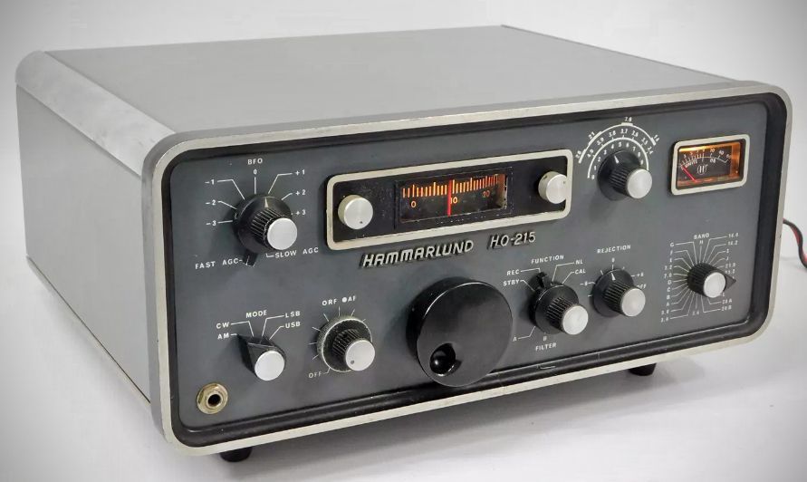
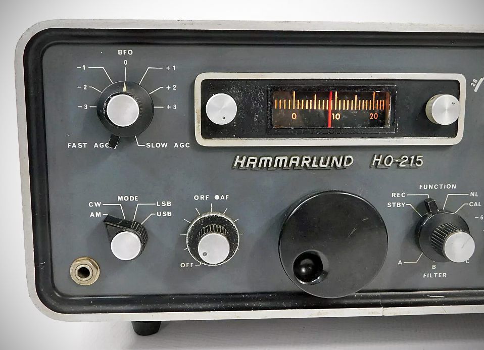
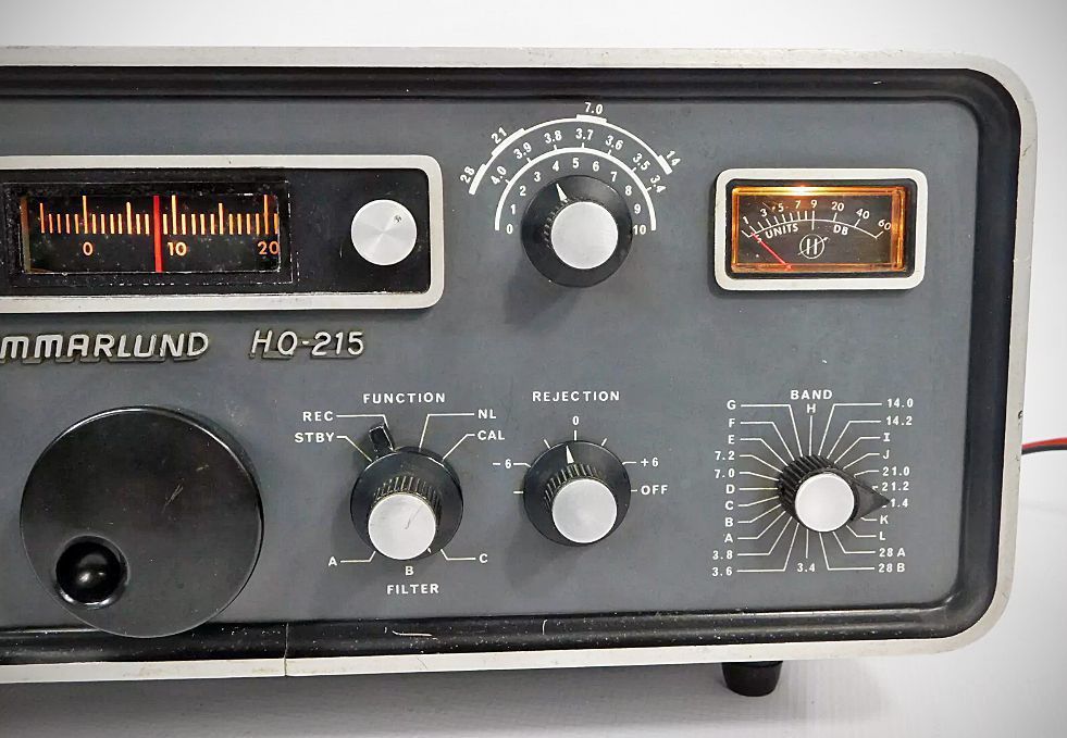
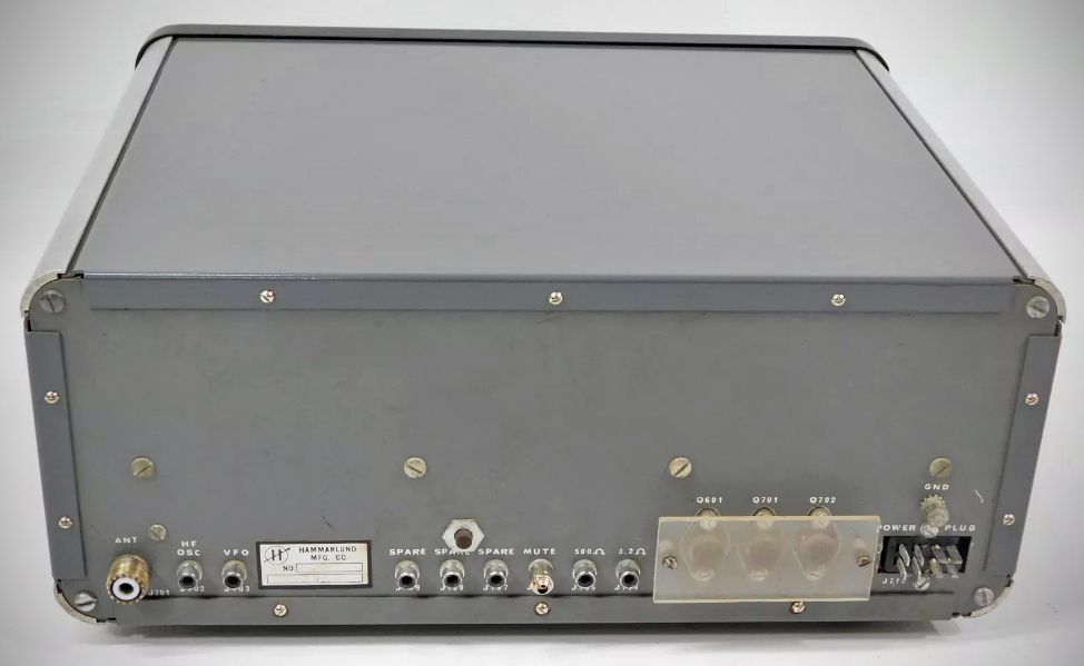
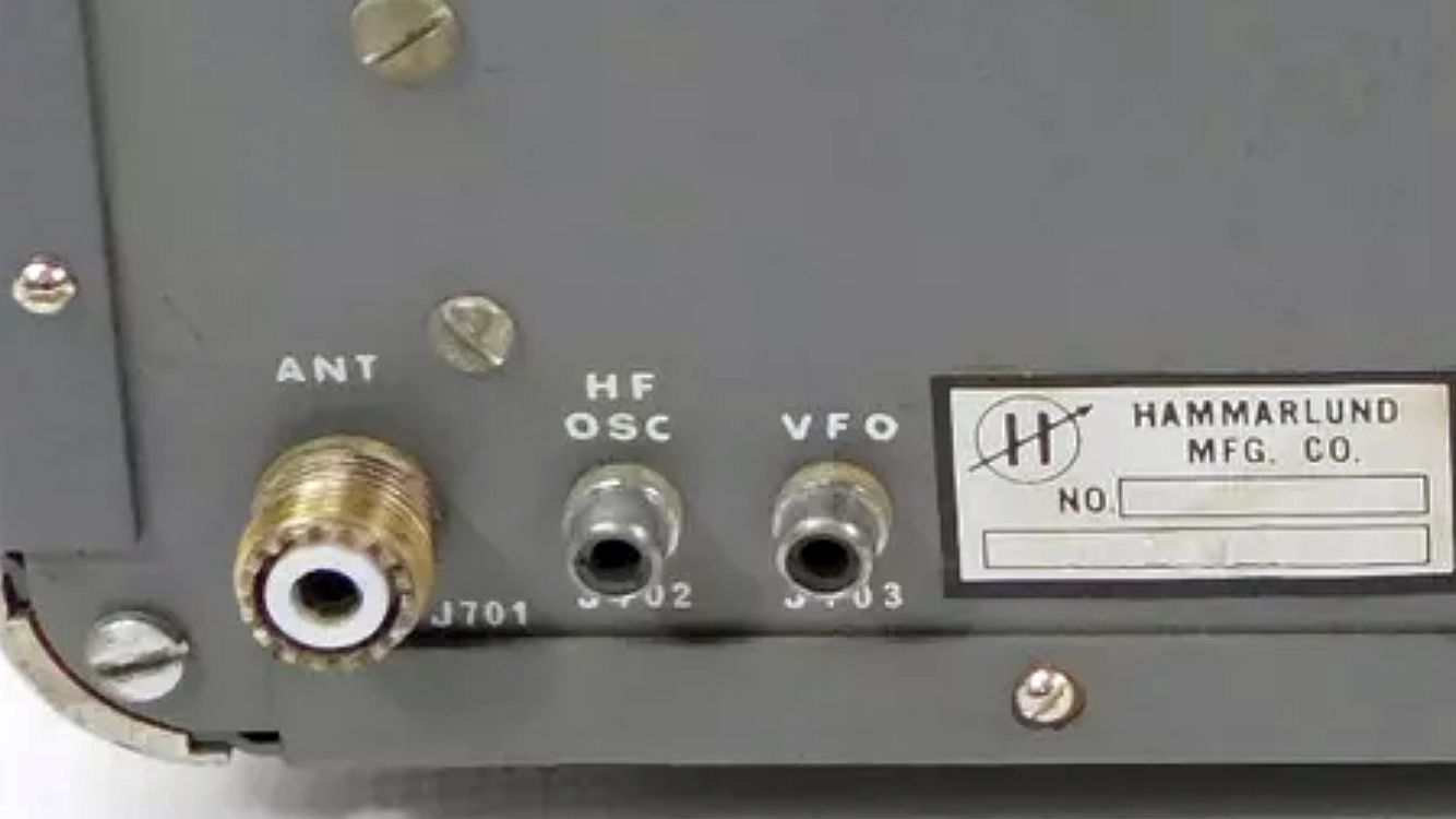
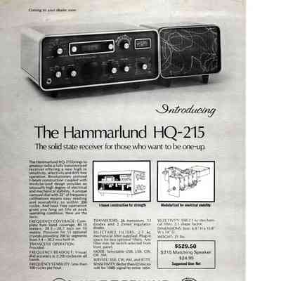
With the proper crystals, the H0-215 could tune any 200 kHz segment between 3.4 and 30.2 MHz. The all-solid-state receiver came equipped with crystals for the 80-15 meter ham bands and 28.5-28.7 MHz on 10 meters. A 2.1 kHz mechanical filter was standard and options included 0.5 and 6 kHz filters. Hammarlund advertised the HQ-215's transceive capability but sold no companion transmitter. The receiver's HF oscillator and VFO frequencies suggest it could have been used with Collins S/Line transmitters; $529.50,
Features
– Fully Solid-State Design.
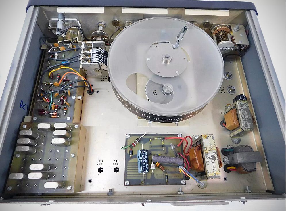
– Carousel Dial: Features 22 inches of frequency calibrations.
– Frequency Coverage: 3.4 MHz to 30.2 MHz continuous coverage capability. Comes with factory-installed crystals for standard amateur bands (80, 40, 20, 15, and 28.5–28.7 MHz on 10 meters).
– Crystal Expansion Provision: Slots for up to 13 additional crystals to cover any 200 kHz band segment between 3.4 and 30.2 MHz without disturbing standard ham bands.
– Transceive Operation: Provision provided for transceiver operation.
– Selectable Operating Modes: USB, LSB, CW, AM, and RTTY.
– Provision to select up to two additional optional filters (e.g., 0.2, 0.5, 0.8, 1.5, 3.1, 4.0, or 6.0 kHz).
Specifications
– Frequency Range: 3.4 MHz to 30.2 MHz continuous coverage capability.
– Factory Band Crystals: 80m (3.4–4.0 MHz), 40m (7.0–7.4 MHz), 20m (14.0–14.4 MHz), 15m (21.0–21.6 MHz), and 10m (28.5–28.7 MHz).
– Auxiliary Crystal Provision: Space for 13 additional crystals to cover any 200 kHz band segment between 3.4 and 30.2 MHz without disturbing standard ham band segments.
– Calibration Accuracy: Better than ±500 Hz between 100 kHz calibration points.
– Visual Dial Accuracy: ±200 Hz on all bands.
– Frequency Stability: Less than 100 Hz per hour drift after a 5-minute warmup.
– Backlash: Not more than 25 Hz.
– Variable BFO: Tunes 452 to 458 kHz.
– Calibrator: 100 kHz Crystal.
– Modes: Selectable USB, LSB, CW, or AM.
– Sensitivity:
SSB / CW Mode: Better than 0.5,muV for 10 dB signal-plus-noise-to-noise ratio (carrier on-off) with 2.1 kHz filter.
AM Mode: 1.0,muV for 10 dB signal-plus-noise-to-noise ratio with 2.1 kHz filter.
– Selectivity:
Standard: 2.1 kHz mechanical filter, 2:1 shape factor.
Optional Filters: Space provided for up to two optional filters (switch-selected from front panel: 0.2, 0.5, 0.8, 1.5, 3.1, 4.0, or 6.0 kHz).
– Rejection Tuning: Provides up to 40 dB rejection of unwanted heterodynes and carriers.
– Cross Modulation & Overload Protection: Equal to or better than vacuum tube receivers of equivalent design.
– Harmonic & Spurious Response: Image rejection better than -50 dB; internal spurious signals below 1.0,muV equivalent signal on all amateur bands.
– Hum and Noise: -40 dB or greater for signals over 1000,muV.
– Automatic Gain Control:
Selectable time constants: Slow and Fast.
Attack time: Less than 5 milliseconds.
Slow release time: 2.0 seconds.
Fast release time: 500 milliseconds.
Curve: Less than 10 dB output change from 2 to 20,000,muV.
– "S" Meter: Approximately 50,muV for S-9 to 60 dB over S-9.
– Noise Limiter: Self-adjusting, series type.
– Audio Output Level: Better than 1.5 watts with less than 10% distortion.
– Audio Response: pm3 dB, 250 Hz to 6.5 kHz.
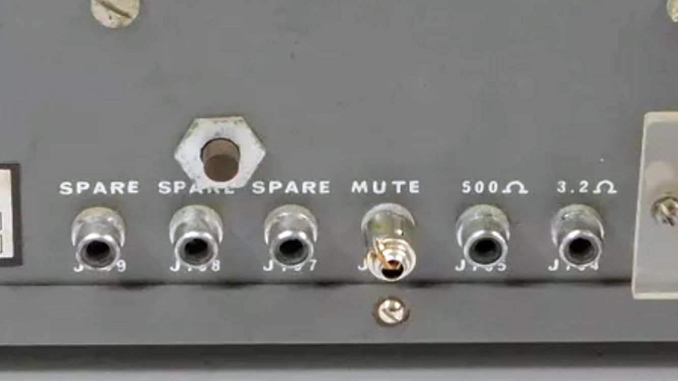
– Audio Outputs: 3.2 Omega Speaker; 500 Omega Headphones and Phone Patch.
– Antenna Input: 50–75 ohms, unbalanced.
– Semiconductor Complement: 26 silicon transistors, 13 diodes, and 2 Zener regulator diodes.
Power Requirements
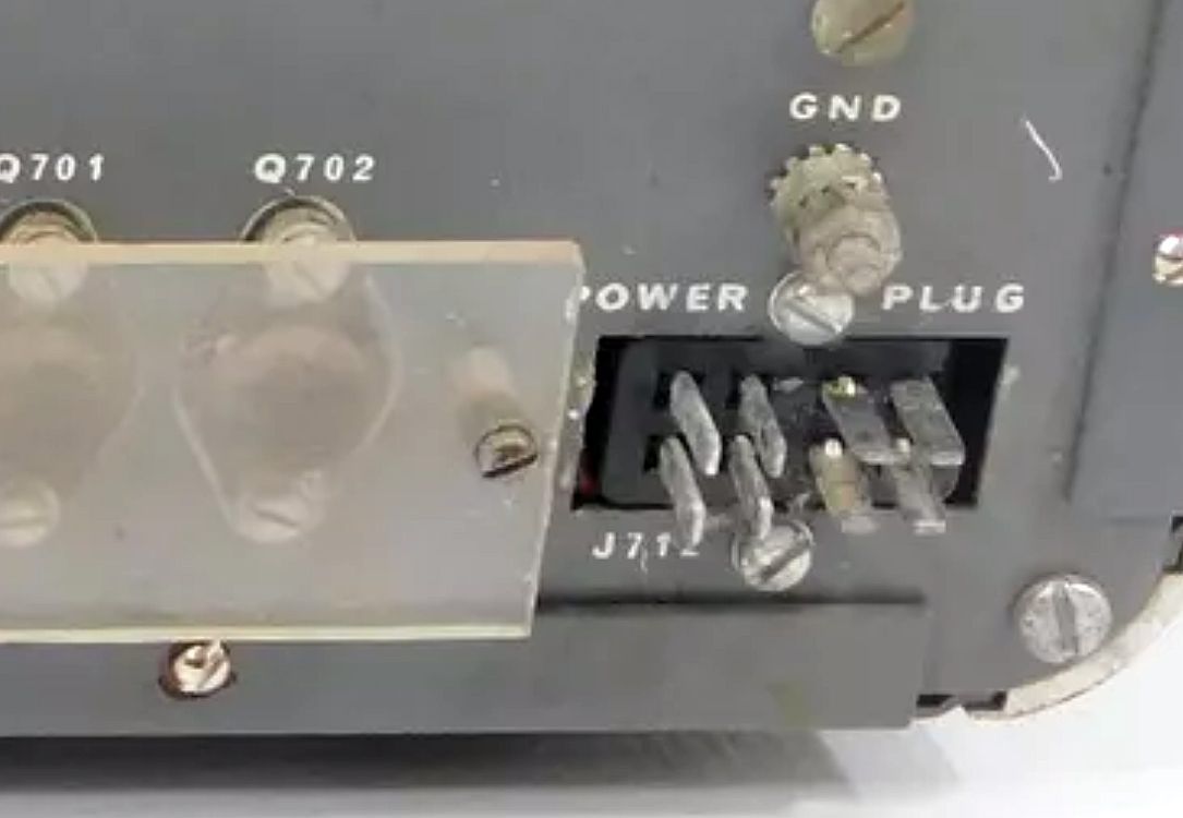
AC: 117/234 VAC, 50/60 Hz, 19 watts
DC: 12–15 V DC, negative ground only, 460 mA, 75 mA with headphones
AC line fused with 3/8 A fuse; DC protected with reverse-polarity diode; Automatic Circuit Breaker.
References
Adding 160 meters. Ham Radio, Jan 1972, p. 32.