Note
CQ, Sep 1961, p. 5.
QST, Nov 1962, p. 107. (info)
73, Dec 1964, inside front cover. (HX-50A)
QST, Jan 1965, p. 109. (HX-50A)
QST, Jan 1966, p. 108.
QST, Oct 1967, p. 139.
QST, Jan 1968, p. 125.
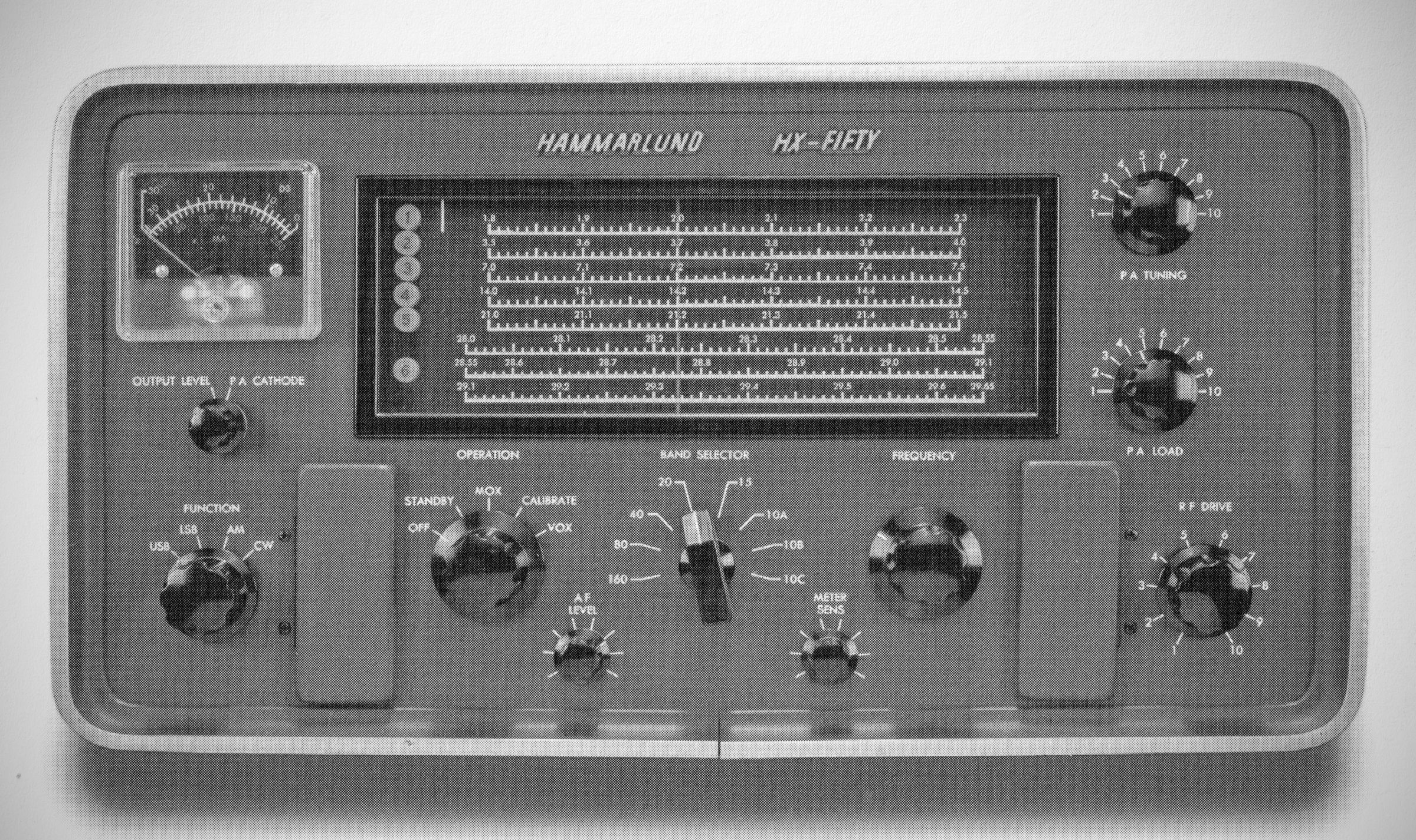
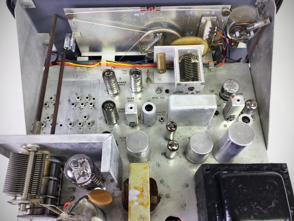
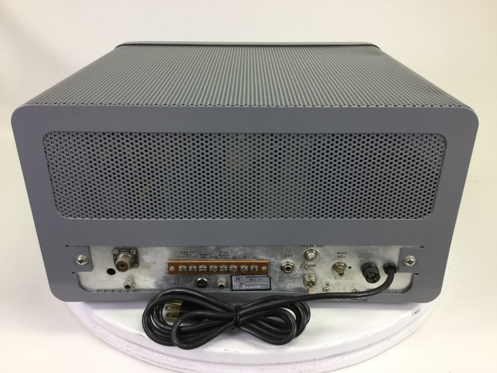
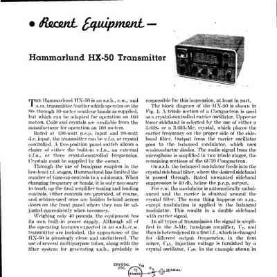
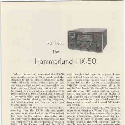
The HX-50 was an AM, CW, and SSB transmitter that used a 3 MHz filter for sideband and ran 130 watts PEP input with a 6DQ5 final. Power input was 90 watts on CW, and 20 watts on AM. it provides full coverage for 80, 40, 20, 15, and 10 meters, along with a 160-meter position available via an optional kit. It also supports operation across MARS, CAP, and CB frequencies.
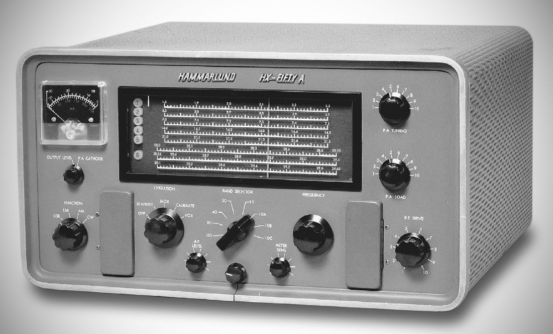
The HX-50A, delivered late in 1964, included three improvements:
1) More power. 200 watts PEP (up from 130 watts)
2) Zero-beat-zero (ZBZ) provides hands-off frequency spotting.
3) CW break-in delay independant of the VOX setting
In all other respects, the two models are identical.
Features
– Employs a dual-conversion design with an internal VFO running from 5950 kHz to 6550 kHz. All other internal oscillators are crystal-controlled.
– Uses a three-element variable Pi-network matching 40 to 80 ohm loads.
– Equipped with a illuminated slide-rule dial calibrated in 10 kHz increments with readability to approximately 2 kHz. Frequency drift after warmup is under 250 Hz.
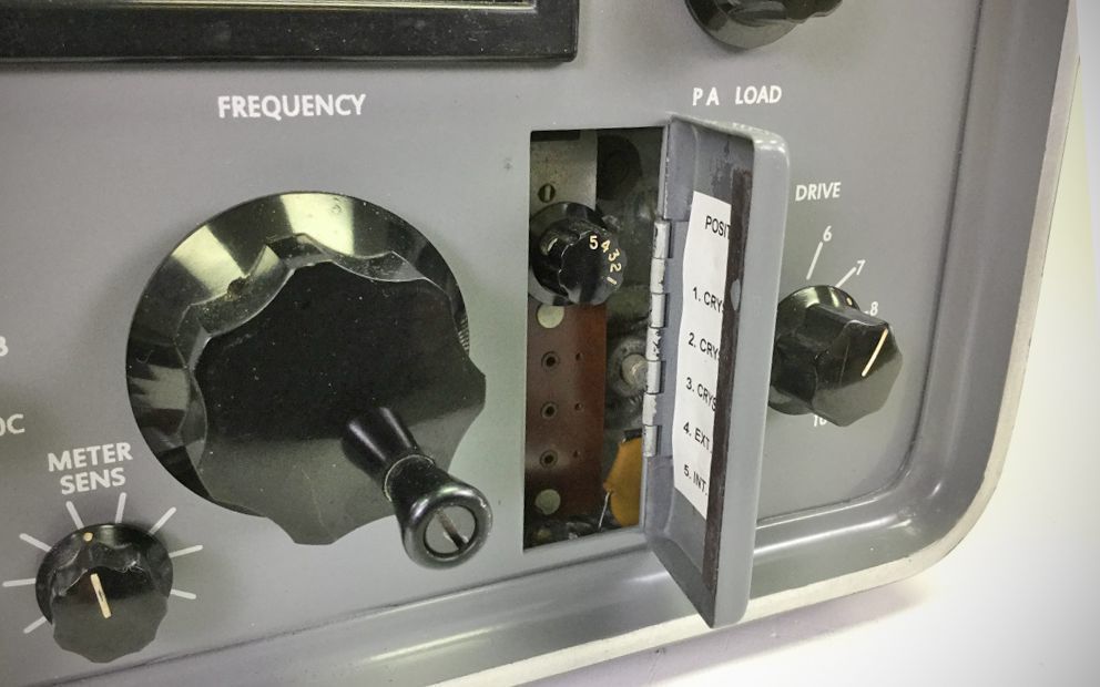
– A front-panel selector switch allows switching between the internal VFO, external VFO, or three crystal-controlled channels.
– Features grid-block sequence keying for clean CW break-in operation, built-in antenna changeover circuitry, and comprehensive VOX with anti-trip controls.
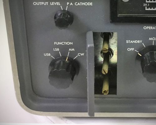
– Secondary adjustments—including VOX delay, anti-trip sensitivity, CW delay, crystal sockets, and the crystal/VFO switch—are accessibly located behind hinged front-panel doors.
Specifications (HX-50)
– Amateur Bands Covered: 80, 40, 20, 15, and 10 meters plus most MARS, CAP, CB and Novice. 160 meter operation optional.
– Calibrated Frequency Ranges: 3.5 to 4.0 MHz; 7.0 to 7.3 MHz; 14.0 to 14.35 MHz; 21.0 to 21.45 MHz; 28.0 to 28.55 MHz; 28.55 to 29.1 MHz; 29.1 to 29.65 MHz.
– Pass Band Coupler: This design provides minimum of 1 MHz bandwidth; thus crystal controlled or external VFO operation provides the following frequency ranges: 3.2 to 4.2 MHz; 6.9 to 7.9 MHz; 13.8 to 14.8 MHz; 20.8 to 21.8 MHz; 27.0 to 31.0 MHz.
– Operating Modes & Power Output: Rated for 130 watts PEP and CW input (90 watts DC). RF output power ranges from 65 watts on 80 meters down to 50 watts on 10 meters for SSB and CW, with AM output at 25% of SSB/CW values.
– Filter bandwidth measures 2.7 kHz at 6 dB down and 4.5 kHz at 50 dB down. Carrier and unwanted sideband suppression are rated at 50 dB or better, with intermodulation distortion at -35 dB minimum.
– Tuning Accuracy: Slide rule dial calibrated every 10 KHz.
– Number of Frequency Conversions: Two.
– Output Network: Pi type, three elements variable. Impedance 40–80 ohms.
– VFO Stability: Better than 250 cycles after warmup.
– Internal VFO Frequency Range: 5950 KHz to 6550 KHz.
– All Other Oscillators: Crystal controlled.
– Metering: Relative RF output and final stage cathode current selectable.
– CW Keying: Grid block bias sequence keying.
Tube Complement (9 total)
– 6C10: Compactron speech amp., modulator, carrier oscillator
– 6EW6: 3 MHz IF amplifier
– 6AW8: First mixer, HF crystal oscillator
– 12AT7: VOX relay and anti-trip amplifier
– 6BV8: VOX amplifier and rectifier
– 12BY7-A: Driver
– 6DQ5A: Linear class AB1 power amplifier
– OA2: Voltage regulator, VFO crystal oscillator, AB1 amplifier screen
– 5R4GYB: High voltage rectifier (tube)
– CER72C: Low voltage rectifier (silicone diode)
– CER70A: Bias voltage rectifier (silicone diode)
Power Requirements: 105–125 VAC, 50/60 Hz, 250 watts at maximum CW output.
References
Review: QST, Mar 1963, p. 50.
Review. 73, Jul 1963, p. 26.
Brief description. Electronics World, Nov 1963, p. 106.
More output. CQ, Dec 1964, p. 30.
Adding MARS. 73, May 1966, p. 104.