Note
QST, Jan 1950, p. 105.
QST, Jun 1950, inside back cover.
Allied Radio catalog 1951 (copyright 1950), p. 138.
QST, Nov 1950, p. 83. (HRO-50R)
QST, May 1951, inside back cover. (HRO-50-1)
QST, Jun 1951, p. 103. (HRO-50-T1)
Allied Radio catalog 1952 (copyright 1951), p. 137.
QST, Mar 1950, inside back cover.
QST, Aug 1950, inside back cover.
QST, Jun 1951, inside back cover.
QST, Sep 1951, p. 117.
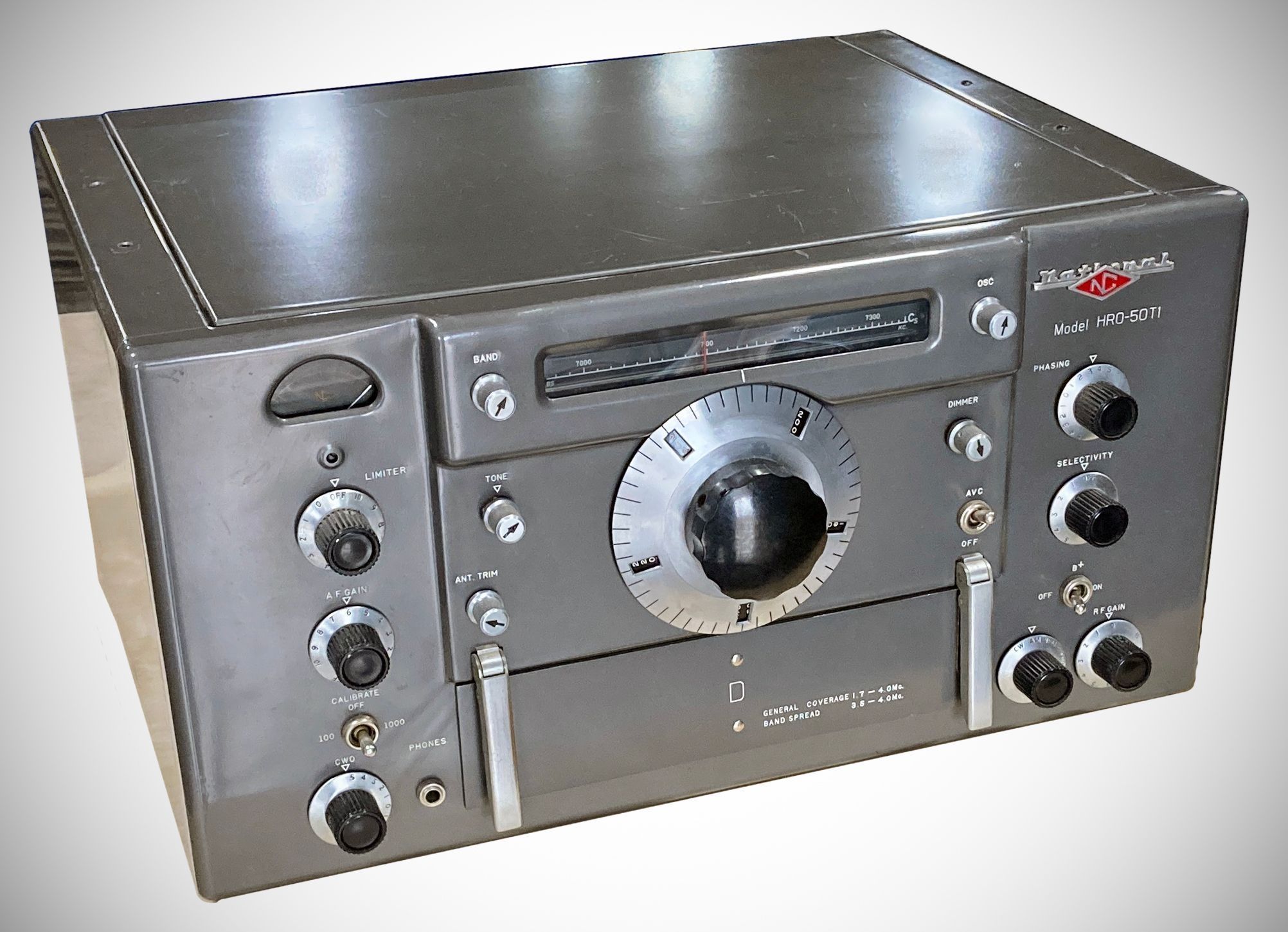
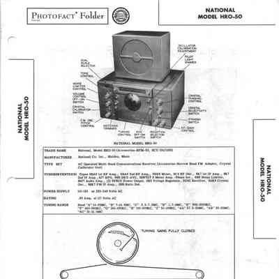
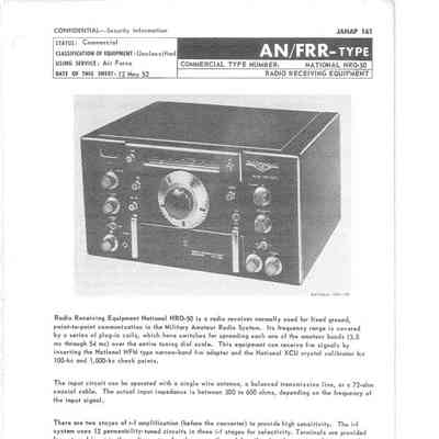
The National HRO-50 was introduced in 1950 as a replacement for the HRO-7, and was a major design departure from previous models, most notably in the shift to a built-in power supply and even more significantly, to a direct-reading dial scale.
The HRO-50 was the first in the HRO series to feature a large, edge-lit linear slide-rule dial illuminating the top of the front panel. While the PW micrometer dial did the heavy lifting for precise tuning, the slide-rule dial acted as a convenient visual indicator to show roughly where you were in the spectrum.
Still, like previous HRO models, the HRO-50 retained the plug-in coil scheme to facilitate band changes.
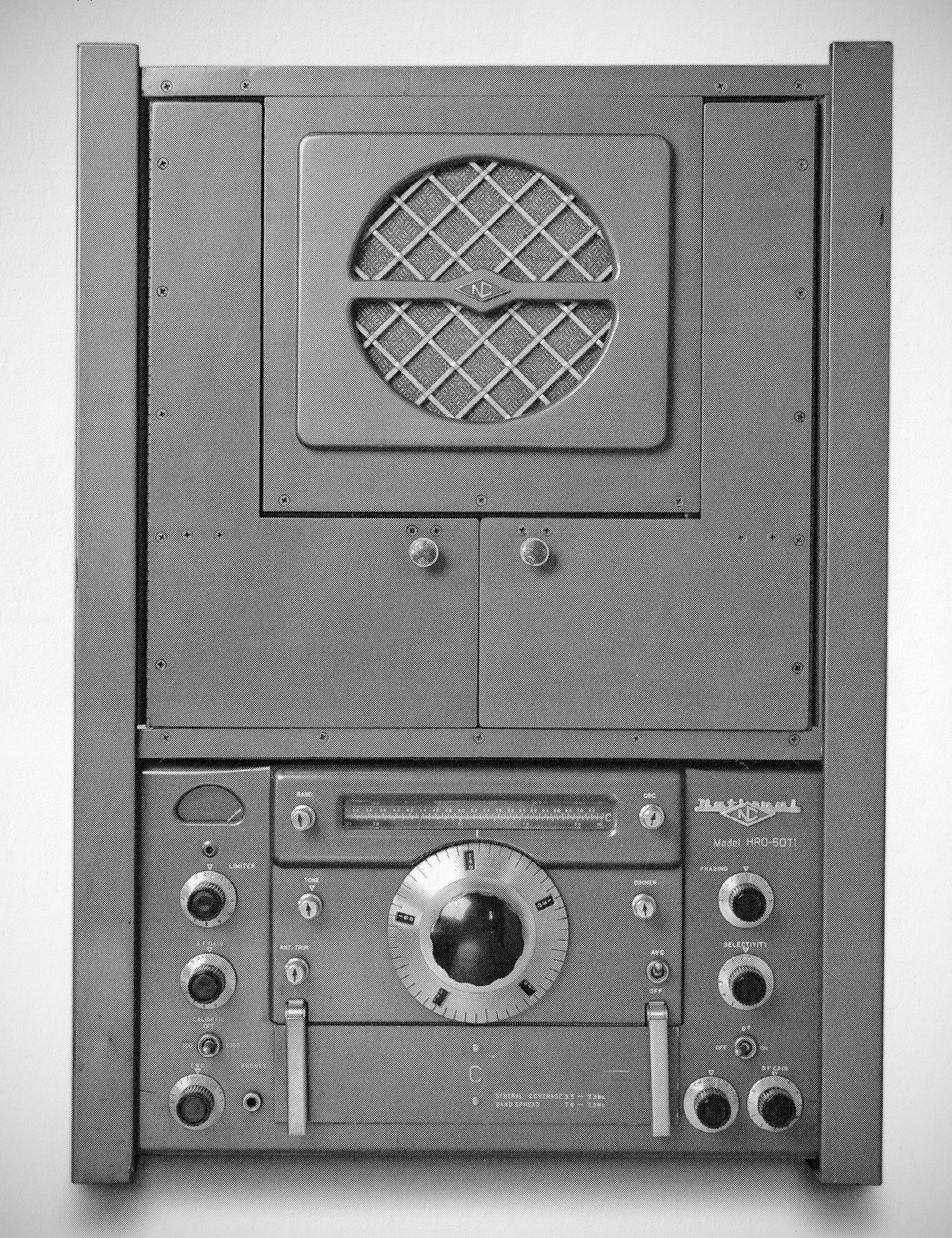
Available as the HRO-50T (tabletop) and HRO-50R (rack mount).
Note that the HRO-50 is outwardly indistinguishable from the HRO-60, making it easy to confuse one for the other.
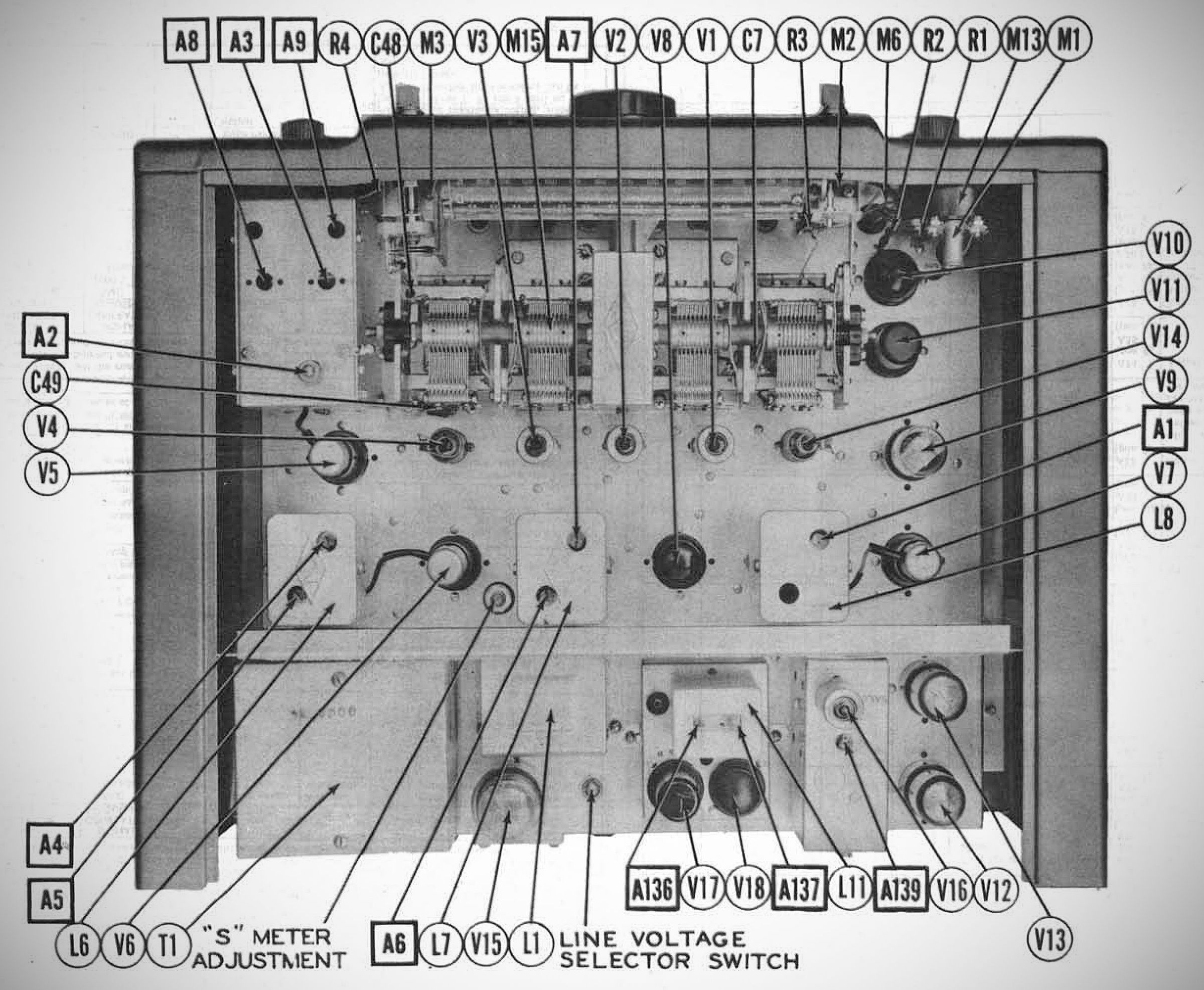
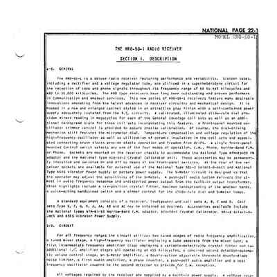
The HRO-50 is a deluxe radio receiver designed for high performance and versatility. It employs a superheterodyne circuit featuring 15 tubes (16 in 50-1), which include a dedicated rectifier and a voltage regulator tube.
Changes in the 50-1
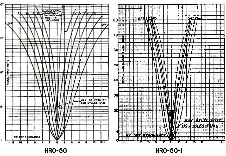
National made a few improvements in the 50-1. These include the addition of a third IF amplifier stage (which added a tube), and changed the second IF amplifier tube from a 6K7 to a 6SG7. National also switched to the use of dual-section (double-tuned) IF transformers.
These changes resulted in a marked improvement in selectivity.
Basic Features of Both Models
– Frequency Range: 50 to 430 kHz and 480 to 35 MHz.
– Tuning & Calibration: Precise calibration is maintained via a front-panel mounted oscillator trimmer control, and the tuning mechanism retains the classic micrometer dial.
– Stability: To ensure stable operation and mitigate frequency drift, the receiver incorporates temperature compensation, voltage regulation for the high-frequency oscillator, and ceramic insulation within the coil sets and connecting brush blocks.
– Operation Modes: A single front-panel control switch allows the operator to quickly select between four distinct modes: CW, AM, Narrow-Band FM, or Phono (an external audio input).
Standard Equipment & Accessories:
The standard setup package includes the Receiver, a Loudspeaker, and four primary coil sets (Types A, B, C, and D).
For expanded capabilities, several optional accessories and additional coil sets (Types E, F, G, H, J, AA, AB, and AC) can be used.
The receiver chassis features built-in provisions to mount internal upgrades, such as the NFM-50 Narrow-Band FM adapter and the XCU Crystal Calibrator, alongside compatibility with the Select-O-Ject (30J-3) and the 650-S Vibrator Power Supply.
Features
– Direct Frequency Reading Illuminated (dimmable) Slide-Rule Dial
– Twelve Tuning Bands Accurately Calibrated
– Calibrated Bandspread for 10-11, 15, 20, 40 and 80 meter Amateur Bands
– High Sensitivity
– Exceptional Stability
– Excellent Signal to Noise Ratio
– Flexible Crystal Filter with Six Positions of Selectivity
– Automatic, Adjustable Threshold, Double Action Noise Limiter
– High-Fidelity, Push-Pull Audio Amplifier
– Provisions for mounting NBFM adaptor and crystal calibrator units within receiver
– Temperature Compensation
– Plug-In Coils for Efficiency and Flexibility
– Built-In Power Supply
Specifications
– Receiver Type: Single-conversion superheterodyne
– Circuit Design: 15 tubes (including a dedicated rectifier and voltage regulator)
– Frequency Coverage: 50–430 kHz and 480 kHz–35 MHz via plug-in coil sets
– Tuning Ratio: 20:1 reduction ratio via a spring-loaded split worm drive (designed to eliminate backlash)
– Effective Scale Length: Approximately 12 feet across 10 full rotations of the micrometer dial
– Operating Modes: CW, AM, NBFM (with optional internal accessory board), and Phono
– Intermediate Frequency (IF): 455 kHz
– Sensitivity: Better than 1.0 µV for a 6 dB Signal-to-Noise ratio
– Antenna Input Impedance: 50 to 200Ω (balanced or unbalanced screw terminals)
– Audio Output Power: 8 watts maximum
– Output Impedance: 8Ω and 500Ω terminals on the rear chassis
– Selectivity Modes: 6-position adjustable crystal filter (from about 15 kHz to 400 Hz)
– Noise Limiter: Automatic, adjustable threshold, double-action type
– Drift Mitigation: Temperature-compensated circuits coupled with high-frequency oscillator voltage regulation (actual values are not stated)
Matching Speaker: National 50TS (external, permanent-magnet dynamic speaker; no speaker is built into the receiver cabinet)
Power requirements
115V or 230 VAC, 50/60 Hz
Optional 6 VDC vibrator power supply
Coil Set General Coverage Bandspread
A 14.0 – 30.0 MHz. 27.0 – 30.0 MHz.
B 7.0 – 14.4 MHz. 14.0 – 14.4 MHz.
C 3.5 – 7.3 MHz. 7.0 – 7.3 MHz.
D 1.7 – 4.0 MHz. 3.5 – 4.0 MHz.
E 900 – 2050 kHz . — —
F 480 – 960 kHz. — —
G 180 – 430 kHz. — —
H 100 – 200 kHz. — —
J 50 – 100 kHz. — —
AA — — 27.5 – 30.0 MHz.
AB 25.0 – 35.0 MHz.
AC — — 21.0 – 21.5 MHz.
(Note: In standard equipment packages, only coil sets A, B, C, and D were supplied with the receiver; the remaining sets were offered as optional accessories.)
(Note: HRO-50 coil sets are not compatible with HRO-60 coil sets)
Tube Lineup
HRO-50 HRO-50-1
First R.F. Amplifier 6BA6 6BA6
Second R.F. Amplifier 6BA6 6BA6
Mixer 6BE6 6BE6
High-Frequency Oscillator 6C4 6C4
First I.F. Amplifier 6K7 6K7
Second I.F. Amplifier 6K7 6SG7
Third I.F. Amplifier ----- 6SG7
Second Detector - A.V.C. 6H6 6H6
Noise Limiter 6H6 6H6
S-Meter Amplifier - Phase Inverter 6SN7GT 6SN7GT
First A.F. Amplifier 6SJ7 6SJ7
Audio Output (2) 6V6GT 6V6GT
Beat Frequency Oscillator 6J7 6J7
Voltage Regulator 0B2 0B2
Rectifier 5V4G 5V4G
References
See notes from National: QST, Jun 1950, p. 65.
See notes from National: QST, Aug 1950, p. 57.
See notes from National: QST, Sep 1950, p. 69.
See notes from National: QST, May 1951, p. 77.
See notes from National: QST, Apr 1952, p. 75.