Note
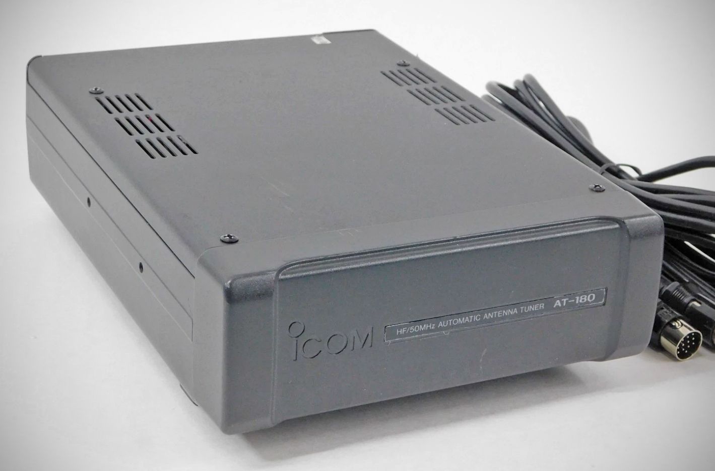
The Icom AT-180 is an Automatic Antenna Tuner designed to automatically match the IC-706MKIIG transceiver to a connected antenna. The tuner operates across both HF and 50 MHz bands , but it is important to note that it cannot be used for the 144/430 MHz band.
Features
– Automatic Preset Memory: Once the tuner successfully matches an antenna, it memorizes the variable capacitor angles as a preset point for each frequency range in 100 kHz steps. When you change the frequency range, the tuner automatically adjusts the capacitors to the saved preset point.
– HF Band Auto-Tuning: During transmission on the HF band, the antenna is automatically tuned if the antenna SWR exceeds 1.5:1.
– 50 MHz Band Tuning: For the 50 MHz band, tuning is initiated manually by pushing and holding the [TUNER] button.
– Manual Tuning Override: Manual tuning is available and particularly helpful during SSB operation on HF bands at low voice levels, where the tuner might not automatically adjust correctly.
– Selectable Operating Conditions: The AT-180 features an internal switch system (S1 and S2) that allows users to select between three specific HF band operating conditions based on their antenna setup:
Normal Condition (Default): The tuner only activates when the SWR is higher than 1.5:1, ensuring tuning only happens when necessary.
hrough Inhibit: Allows the tuner to attempt matching even with poor SWR (up to 3:1 after tuning). It automatically starts if VSWR exceeds 3:1, but manual tuning is required each time you change the frequency.
Tuner Sensitive Condition: The tuner activates every time you transmit to guarantee the lowest possible SWR at any given time (for SSB mode, it defaults back to the "Through Inhibit" condition).
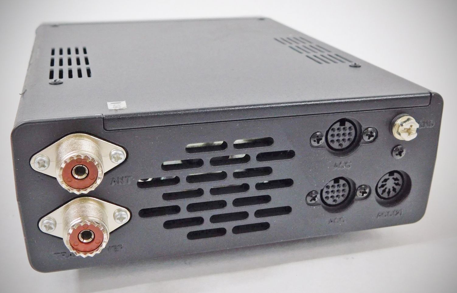
The Icom AT-180 features three DIN-style connectors on the rear panel that serve distinct roles for control, data, and power.
1. ACC (13-pin DIN): This is the primary control interface. It connects directly to the ACC socket on the back of your transceiver using the supplied 13-pin cable. It serves three main purposes:
Power: It provides the 13.8V DC required to run the tuner's motors and logic board.
Control: It handles the handshake between the radio and tuner, such as the "START" signal when you push the tuner button and the "KEY" signal to tell the radio to transmit a low-power carrier for tuning.
ALC (Automatic Level Control): It passes the ALC voltage back to the radio to protect the final transistors during the tuning process.
2. DATA (6-pin DIN): This socket is used for frequency data communication.
Function: It allows the tuner to "read" the operating frequency of the transceiver. This enables the Preset Memory feature. When you change bands on your radio, the tuner detects the change through this port and automatically moves the internal variable capacitors to the previously saved position for that frequency range, even before you start transmitting.
3. ACCESSORY (7-pin DIN): This is a "pass-through" or "daisy-chain" port.
Function: Since the AT-180 occupies the main ACC port on your transceiver, this 7-pin socket allows you to connect additional external equipment (such as a linear amplifier or a TNC for digital modes) without needing a Y-adapter or splitter. Note: It carries a subset of the signals found in the main 13-pin ACC port, specifically those most commonly needed by external peripherals like PTT (Push-To-Talk) and ALC.
Note: NEVER transmit with the tuner turned ON if an antenna is not connected, as this will damage both the transceiver and the antenna tuner.
Specifications
– Frequency Coverage: 1.9–54 MHz
– Input Impedance: 50 Ω
– Maximum Input Power: 120 W
– Minimum Tuning Power: 8 W
– Matching Impedance Range:
16.7–150 Ω (HF band)
20–125 Ω (50 MHz band)
– Tuning Accuracy: Less than SWR 1.5:1
– Insertion Loss: Less than 1.0 dB (after tuning)
Power Supply Requirements: 13.8 V DC / 1 A (supplied directly from the transceiver's ACC socket)