Note
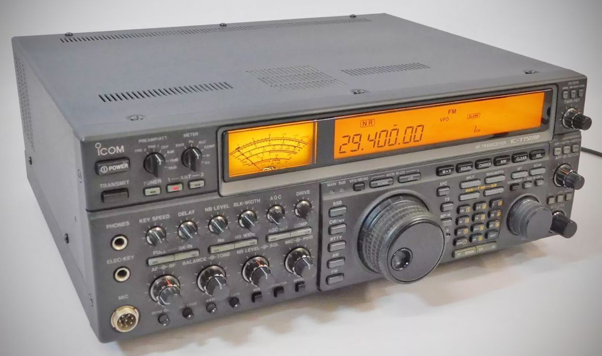
The IC-775 series transceivers replaced Icom's IC-756. The 775 and 775DSP are sophisticated fixed station that provide comprehensive coverage across the HF spectrum. They are built with a focus on high-fidelity reception and powerful transmission capabilities, featuring a large, informative front panel with a multi-function display and a wide array of dedicated controls for precise adjustments. The transceivers are designed to be the centerpiece of a modern amateur radio shack, offering seamless integration with various accessories like external speakers, linear amplifiers, and antenna tuners.
The primary difference between the two models lies in their digital signal processing (DSP) capabilities. The IC-775DSP is the includes a factory-installed UI-100 DSP unit. This unit enables advanced digital functions such as automatic notch filtering and sophisticated noise reduction, which are controlled via dedicated knobs on the front panel. While the standard IC-775 shares most of the same hardware and layout, it does not include these DSP features out of the box; however, it can be upgraded to match the DSP model's performance by installing the optional UI-100 DSP unit later.
Discontinued in 2003. Replaced by the IC-7800.
General System Features
– Operating Modes: Supports SSB (USB/LSB), CW, RTTY (FSK), AM, and FM.
– Dual Receiver Capability: Features a Dualwatch function that allows simultaneous reception of two different frequencies (MAIN and SUB readouts) within the same band.
– Triple Band Stacking Register (TBSR): Memorizes three different frequencies and modes for each band, allowing for quick recall of recently used settings.
– High Power Output: Provides a continuously variable RF output from 5 W to 200 W (AM mode is limited to 5 W to 50 W).
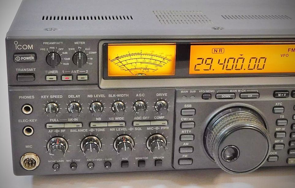
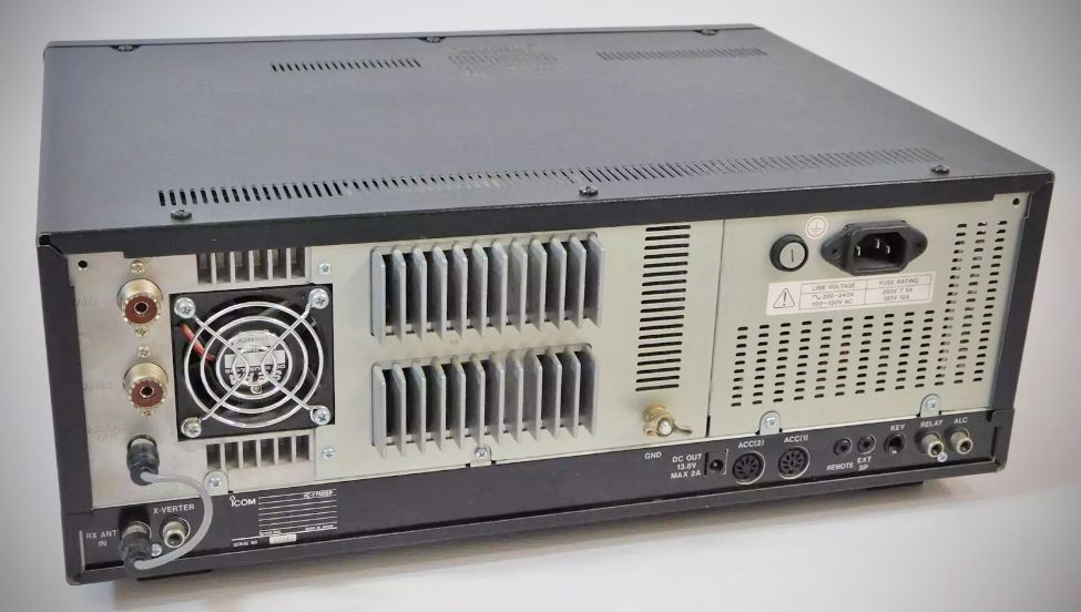
– Antenna Management: Includes two antenna connectors with programmable selection based on the operating band.
– Built-in Antenna Tuner: Features an automatic antenna tuner that can be manually triggered or bypassed. It automatically bypasses if a match cannot be found within 20 seconds.
Receiver & Signal Processing
– Digital Signal Processing (DSP): Standard on the IC-775DSP (optional for the IC-775), providing advanced noise reduction and auto-notch capabilities.
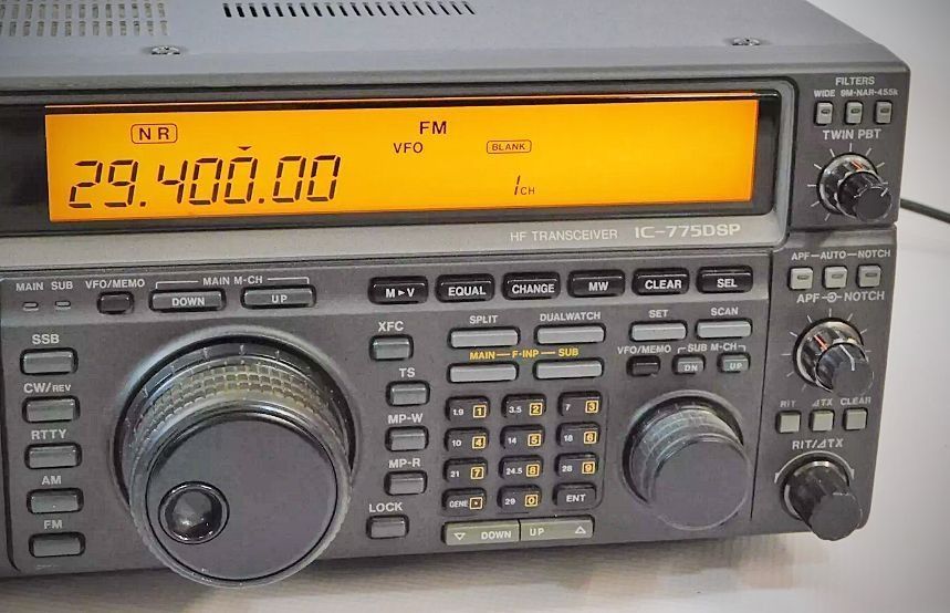
– Twin Passband Tuning (PBT): Allows for electronic narrowing of the IF passband to eliminate interference from nearby signals.
– Noise Blanker (NB): Features a multi-level and wide-width noise blanker specifically designed to reduce pulse-type interference like ignition noise or "woodpecker" signals.
Preamps and Attenuators:
– Preamp 1: 10 dB gain for all HF bands.
– Preamp 2: 16 dB high-gain preamp for frequencies above 21 MHz.
– Attenuators: Switchable 6 dB, 12 dB, or 18 dB settings to prevent distortion from strong local signals.
– Automatic Gain Control (AGC): Features an adjustable time constant (Fast to Slow) and a manual deactivation switch for receiving weak signals near strong ones.
– Audio Peak Filter (APF): Provides an 80 Hz passband filter to pick out CW signals from heavy interference.
CW & Digital Operation
– Electronic Keyer: Includes a built-in electronic keyer with adjustable speed (7 to 41 wpm), reversible polarity, and a 3-channel memory keyer.
– Break-in Operation: Supports both Full Break-in (QSK) for monitoring signals between keying pulses and Semi Break-in with adjustable delay.
– CW Reverse Mode: Allows the operator to switch the sideband used for CW reception to help avoid interference.
– Pitch Control: Adjustable CW audio pitch for comfortable listening without changing the operating frequency.
Frequency Control & Navigation
– Tuning Steps: Supports quick tuning in programmed kHz steps or fine-tuning in 1 Hz steps.
– RIT and ΔTX: Receiver Incremental Tuning and Transmit Incremental Tuning allow for frequency shifts up to ±9.999 kHz in 1 Hz or 10 Hz steps.
– Quick Split: Instantly equalizes the transmit frequency to the receive frequency for split-frequency DXing.
– Channelized Split: Changes the transmit frequency in programmed steps while maintaining the receive frequency.
– Memory Channels: Includes 99 regular memory channels and additional scan edge channels.
– Memo Pads: Dedicated memory for temporary storage of 5 to 10 frequencies and modes for immediate recall.
Convenience & Maintenance
– Voice Synthesizer (Optional): When the UT-66 is installed, the transceiver can announce the operating frequency and mode.
– Set Modes: Includes P-set (Push-set) and H-set (Hold-set) menus for customizing deep-level system settings.
– S/RF Metering: Multi-function meter displays SWR, Relative RF Power, ALC level, Compression level, and Final FET Drain Current/Voltage.
– Dial Lock: Electronic locks for both the Main and Sub tuning dials to prevent accidental frequency changes.
General Specifications
– Operating Modes: SSB (USB/LSB), CW, RTTY (FSK), AM, and FM.
– Number of Memory Channels: 99 regular channels plus additional scan edge channels.
– Antenna Impedance: 50 Ω (nominal).
– Operating Temperature Range: −10∘C to +60∘C (+14∘F to +140∘F).
– Frequency Stability: Less than ±100 Hz from 1 to 60 minutes after power ON; after that, less than ±20 Hz at +25∘C (±77∘F).
Transmitter Specifications
– Output Power:
SSB, CW, RTTY, FM: Continuously variable from 5 W to 200 W.
AM: Continuously variable from 5 W to 50 W.
– Spurious Emissions: Less than −60 dB.
– Carrier Suppression: More than 40 dB.
– Unwanted Sideband: More than 55 dB.
– Microphone Impedance: 600 Ω.
Receiver Specifications
– Receive System: Triple conversion superheterodyne (quadruple conversion for FM).
– Sensitivity (typical):
SSB, CW, RTTY (10 dB S/N): 0.16 μV (1.8–29.99 MHz, Preamp 1 ON).
AM (10 dB S/N): 2.0 μV (1.8–29.99 MHz, Preamp 1 ON).
FM (12 dB SINAD): 0.5 μV (28–29.99 MHz, Preamp 1 ON).
– Squelch Sensitivity: SSB, CW, RTTY: Less than 5.6 μV.
FM: Less than 1.0 μV.
– Selectivity:
SSB, CW, RTTY: More than 2.4 kHz/−6 dB; Less than 3.8 kHz/−60 dB.
AM: More than 6.0 kHz/−6 dB; Less than 15.0 kHz/−60 dB.
FM: More than 12.0 kHz/−6 dB; Less than 20.0 kHz/−60 dB.
– Spurious and Image Rejection: More than 70 dB (except IF through in 7 MHz band).
– Audio Output Power: More than 2.6 W at 10% distortion with an 8 Ω load.
– RIT/ΔTX Range: ±9.999 kHz.
Antenna Tuner Specifications
– Matching Impedance Range: 16.7 Ω to 150 Ω unbalanced (less than 3:1 SWR).
– Minimum Operating Input Power: 8 W.
– Insertion Loss: Less than 1.0 dB (after tuning).
Power Supply: The units are designed for AC operation, with different versions available for 100-120 V or 220-240 V line voltages.