Note
QST, Jan 1982, p. 142.
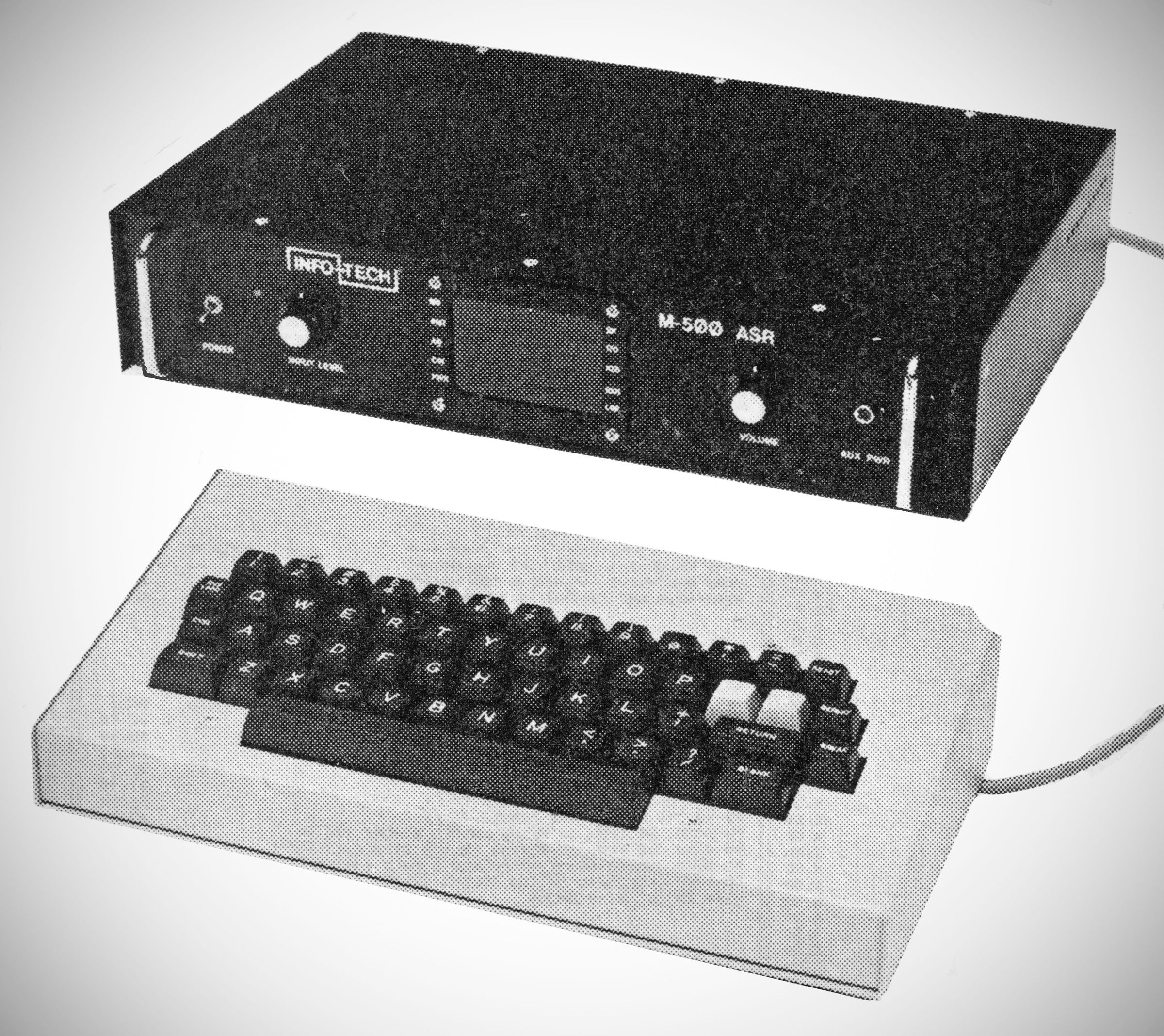
The Info-Tech Model 500 Tri-Mode ASR is a sophisticated digital communications terminal designed for amateur radio operations. It serves as an integrated system for sending and receiving multiple electronic communication formats over radio equipment.
Supported Codes & Data Rates
The M500 functions across three primary data modes, allowing wide flexibility in digital and analog decoding:
– Morse Code: Capable of handling speeds from 5 to over 100 Words Per Minute (W.P.M.).
– Baudot (Murray): Supports speeds of 45, 50, 57, 74, and 100 Baud (corresponding to roughly 60, 66, 75, 100, and 132 W.P.M.).
– ASCII: Can operate via a 7.5-unit code at 110, 150, 300, 600, and 1200 Baud, or an 11-unit code. Parity can be configured to Mark, Space, Even, or Odd.
Transmitting Modes
The unit offers five distinct modes for transmission depending on how the operator prefers to stage and send text:
– Letter Mode: Transmits each letter dynamically as it is typed.
– Word Mode: Holds text locally and transmits each word upon completion.
– Line Mode: Holds text and transmits each line upon hitting completion.
– Buffer Mode: Transmits a pre-loaded buffer memory upon command.
– Clocked Mode: Controls the output to transmit at a slower rate than normal.
System Memory & Message Handling
– Memory Architecture: The standard configuration features 8K of EPROM and 12K of static RAM. Within the static RAM, 4K is permanently dedicated to the video processing, and 2K can be battery-protected to maintain data. An optional expansion system can provide an additional 2K EPROM and 8K static RAM.
– Messages: Includes space for 10 user-programmable "recallable" messages of 144 characters each. It also holds separate, user-programmable Continuous Wave Identification (C.W.I.D.) and standard I.D. messages of 72 characters each.
– Selective Calling (Sel-Cal): Incorporates a system allowing up to 14 distinct Sel-Cal codes (8 characters each) to trigger internal systems.
– Built-in Tests & Mail Box: Features built-in Quick Brown Fox (QBF) and "RY" test messages across all modes, alongside a local Mail Box function.
Demodulators & Signal Interface
– Morse Demodulator: Employs an active filter and envelope detector, factory set for 1000 Hz but user-adjustable between 750 and 1250 Hz.
– RTTY/ASCII Demodulators: For speeds up to 110 Baud, it employs separate active filters mapped to three classic tone shifts:
– 170 Hz Shift:* Mark at 2125 Hz, Space at 2295 Hz.
– 425 Hz Shift:* Mark at 2125 Hz, Space at 2550 Hz.
– 850 Hz Shift:* Mark at 2125 Hz, Space at 2975 Hz.
– High-speed ASCII (150 to 1200 Baud) utilizes a dedicated active filter demodulator with a single shift (Mark at 2125 Hz, Space at 2975 Hz).
Modulation, Keying, & Outputs
– Morse Keying: All solid-state keying mechanisms capable of driving low-potential circuits (max 30 VDC @ 200 mA) as well as conventional high-voltage Grid or Cathode keying systems (up to ±150V @ 75 mA).
– AFSK/FSK Generation: Uses a derived three-shift function generator for standard RTTY and ASCII speeds. AFSK output is user-adjustable up to 1.5V into a 500-ohm load.
– Printer & Accessory Drivers: Offers fully isolated Loop switching (supporting an external 60–75 mA supply), RS-232, and MIL-188 printer drivers. It can also actively command accessories via open-drain VMOS auto-start outputs.
Display, Indicators, & Physical Properties
– Video Specifications: Generates a split-screen layout displaying 72 characters x 25 lines using a 5x7 upper-case dot matrix. The upper portion shows received text, while a user-programmable 2-to-15 line lower portion displays transmission staging. The 25th line acts as a dedicated Status Line showing system status, a real-time battery-backed clock, and selected operations.
– Hardware Indicators: The front panel includes dedicated status LEDs for Power, Input Limiting, Mark/Space tuning, Morse tuning, Transmit, Auto-start, Shift selection, and a peak-tuning "Cross Display".
Memory Retention: Features an internal battery holder located in the right-rear corner designed for three AA cells to preserve the real-time clock and memory during short-term power drops.
Power requirements: 115 VAC, 50/60 Hz, 70 Watts.