Note
CQ, Mar 1962, p. 11.
73, Dec 1962, p. 27.
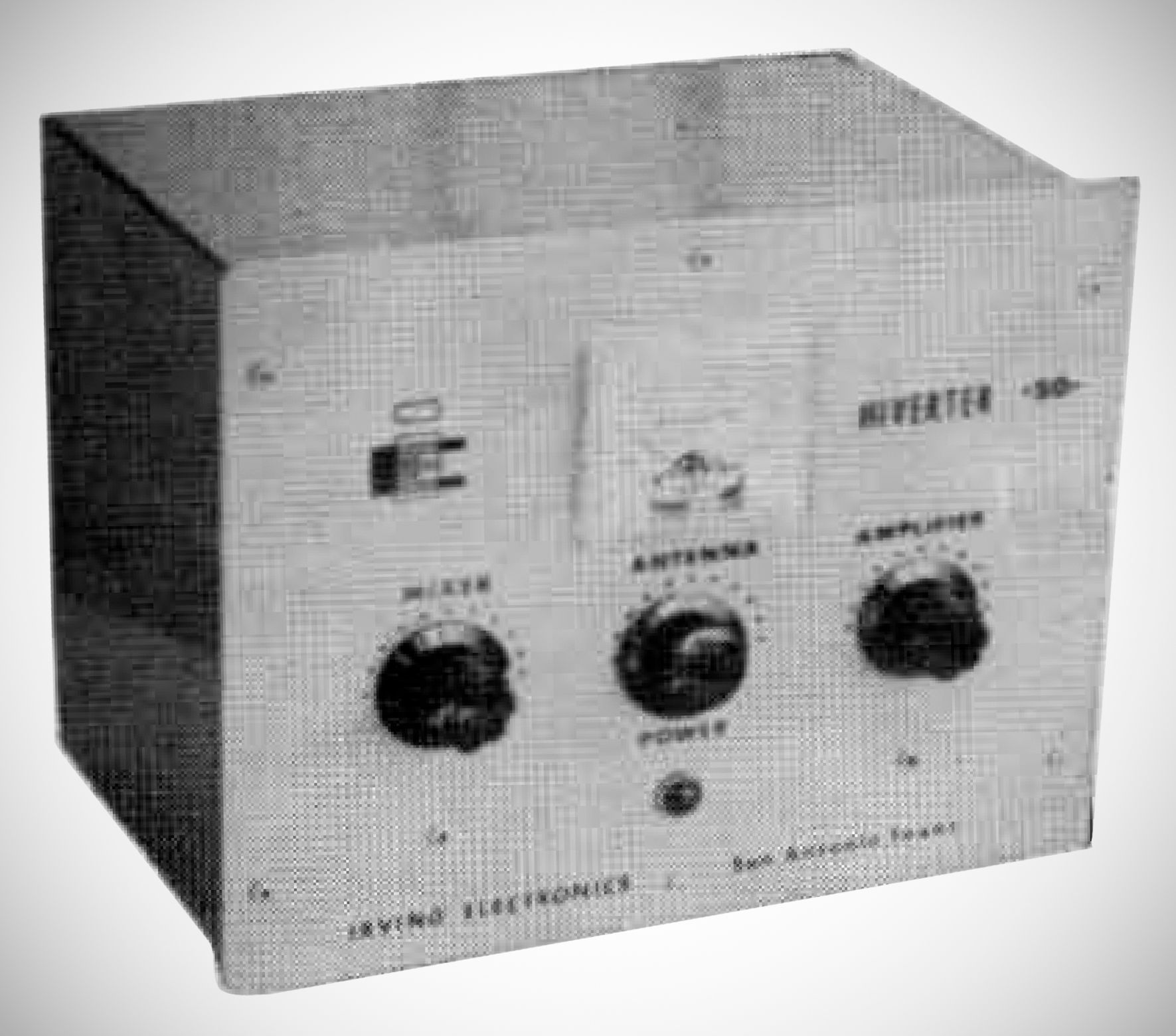
This 50 MHz converter extends use of a 20 meter SSB, AM or CW transmitter to 50 MHz. It will provide about 50 watts PEP input (30 watts output) on sideband, about 40 watts input on AM phone and 50 watts on CW.
Driver Requirements: Operates with driving transmitters producing 10 to 100 watts of 14 MHz RF. It requires roughly 6 watts of drive, so rigs with output above 20 watts require a carrier control or resistive attenuation pad.
Oscillator & Mixer: Uses a 6CL6 tube functioning as a grid-plate harmonic oscillator with an 18 MHz crystal that doubles to 36 MHz. This signal is capacity-coupled to the cathode of a 5763 mixer tube. Mixing a 14.2 MHz input from the 20-meter exciter with the 36 MHz oscillator signal yields a sum frequency of 50.2 MHz in the 6-meter band.
Amplifier Stage: Features a 6146 final amplifier tube operating in Class AB1 or AB2. It includes a series resonant LC circuit tuned to 14 MHz to prevent any 14 MHz feedthrough from reaching the output stage.
Antenna Matching: Utilizes a pi-network output circuit capable of matching 50-to-100-ohm antenna loads.
Construction: Built using internal printed circuit board wiring for ease of maintenance.
Tube lineup:
– 6CL6 Oscillator
– 5763 Mixer
– 6146 RF Amp
– (2) 0B2 Voltage regulatiors
Pi-Net Output to match 50-100 ohm Antenna Load
Power Supply Requirements: (Heathkit HP-20 or similar)
6.3 VAC, 2.7 Amps (Filaments)
300 VDC, 60 Ma. (Osc-Mixer)
600 VDC, 120 Ma. (Amplifier)
–130 VDC, (Amp. Bias)
These volategs could often be tapped from the driving transmitter or supplied by an auxiliary unit like the Heathkit HP-20.