Note
Allied Radio catalog 1954 (copyright 1953), p. 48.
QST, Jan 1954, p. 83.
QST, May 1955, p. 84. (a few details)
Allied Radio catalog 1956 (copyright 1955), p. 197.
Walter Ashe catalog 1957 (probably issued in 1956), p. 4.
Allied Radio catalog 1958 (copyright 1957), p. 269.
Allied Radio catalog 1960 (copyright 1959), p. 402.
Allied Radio catalog 1961 (copyright 1960), p. 398..
Allied Radio catalog 1962 (copyright 1961), p. 279.
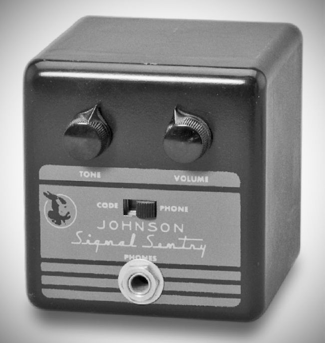
The Signal Sentry served several station functions. It worked as an RF-actuated CW monitor with adjustable tone and volume. A front-panel switch turned it into a phone monitor to check on-the-air signal quality. It provided break-in muting for the station receiver, and with slight modification could be used as a code practice oscillator. The unit used two tubes and required an external power source.
The device's circuit is centered around a 12AU7 tube and an NE-2 neon lamp.
CW Mode: RF energy from the transmitter is rectified by the 12AU7 diode section. The resulting negative voltage cuts off the 12AX7 to mute the receiver while simultaneously triggering the neon lamp relaxation oscillator to produce a monitoring tone.
Phone Mode: The RF is rectified, and the modulation (speech/hum) is fed through a capacitor to the amplifier for monitoring. The oscillator is disabled in this mode to prevent interference with the voice signal.
Standby: When the transmitter is off, the 12AX7 acts as a standard amplifier for the receiver output.
The Signal Sentry is installed by connecting it to a power supply (usually drawing from the receiver), plugging into the receiver's headphone jack, and loosely coupling an RF probe to the transmitter output
Core Functions
The Signal Sentry performs four primary roles in a radio station:
– CW Signal Monitoring: Provides a pleasant, non-tiring tone that follows the keyed signal of the transmitter.
– Phone Monitoring: Demodulates and amplifies the signal to check for audio quality, carrier distortion, and hum.
– "On the Air" Indicator: Because it is triggered directly by transmitter RF energy, it serves as a visual and audible confirmation that the station is transmitting.
– Receiver Muting: Automatically mutes the receiver’s audio when the transmitter is energized, allowing for seamless "break-in" operation.
Specifications
Frequency Range: up to 50 MHz without tuning
Power Requirements: 175–300V DC plate (3 mA) and 6.3V filament
Tubes: (1) 12AX7 (dual amplifier), (1) 12AU7 (oscillator/diode)