Note
QST, Jul 1956, p. 83.
Walter Ashe catalog 1957 (probably issued in 1956), p. 4.
Allied Radio catalog 1957 (copyright 1956), p. 244.
Allied Radio catalog 1960 (copyright 1959), p. 389.
QST, Aug 1963, p. 88.
QST, Apr 1965 p. 5.
Kit or wired.
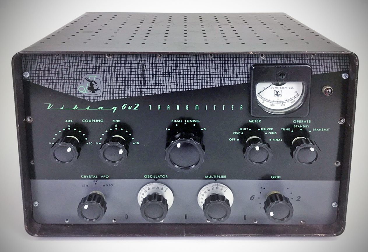
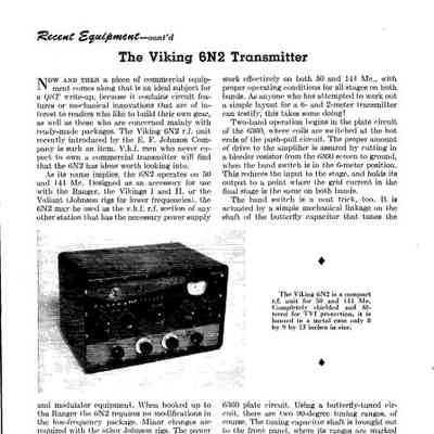
The 6N2 transmitter offered band-switching coverage of 6 and 2 meters. The final amplifier used a 5894 dual tetrode in push-pull. Input power was 150 watts on CW and 100 watts on phone. Introduced as a companion accessory for Johnson’s HF transmitter line—such as the Ranger, Viking I and II, and Valiant—it utilizes the power supply and audio modulator equipment of the host transmitter rather than containing its own.
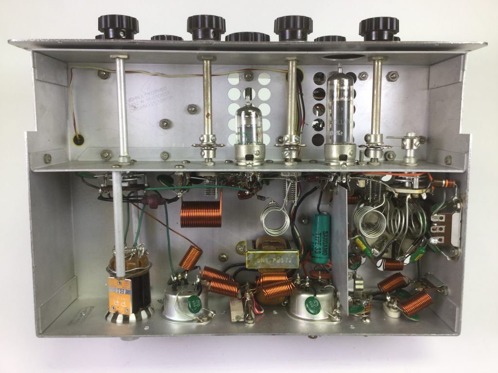
Rather than using a traditional multi-position ceramic switch, band switching between 6 and 2 meters is driven mechanically by the butterfly tuning capacitor for the 6360 driver plate circuit. Because a butterfly capacitor tunes over two 90-degree rotations, one rotation selects 6-meter coils while the opposite rotation switches to 2-meter coils. A screen bleeder resistor automatically engages on 6 meters to equalize drive levels across both bands.
The final amplifier avoids band-switching contact losses by using a shared output circuit:
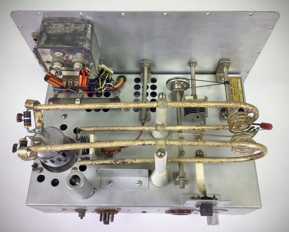
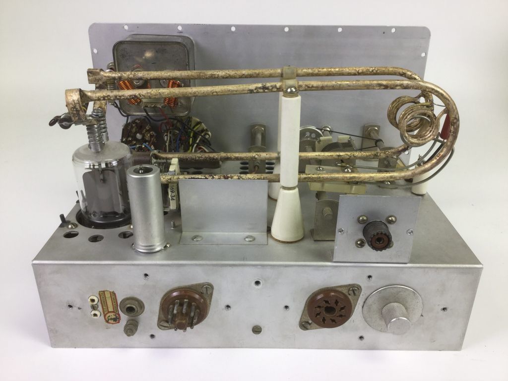
A half-wave parallel transmission line acts as the tuned circuit on 144 MHz.
The 50 MHz plate inductor connects directly to the transmission line at the exact RF voltage node for 144 MHz. Consequently, it is electrically transparent on 2 meters while acting as a standard tuned tank on 6 meters.
Output coupling uses a hybrid hairpin loop (for 144 MHz) and a single-turn coil (for 50 MHz) connected to a series variable capacitor to tune out reactance and adjust loading.
Standard TVI countermeasures include complete internal compartmentation, fully shielded power connectors, filtered external leads, and an internal crystal socket assembly accessible via a rear chassis plug.
Keying & Metering: Grid/cathode keying occurs in the 6360 driver stage using an internal click filter. The shielded panel meter monitors oscillator, multiplier, driver, or final plate currents, along with final grid current, and includes an "Off" position to prevent unnecessary meter movement during CW keying.
Specifications
– Operating Bands: 50–54 MHz (6 meters) and 144–148 MHz (2 meters)
– Power Input Ratings: Up to 150 watts CW or 100 watts AM phone (dependent on external power supply voltage)
Tube Complement:
– 6U8: Pentode section acts as an 8 MHz crystal oscillator/doubler; triode section acts as a tripler to 48–54 MHz.
– 6360: Dual tetrode driver stage operating as a tripler to 144 MHz or straight-through amplifier on 50 MHz.
– 5894A: Twin tetrode final power amplifier operating straight-through on both bands.
– 6AQ5: Screen clamper tube providing protective bias to the final stage when RF drive is interrupted.
Power Requirements
Filament: 6.3 volts at 3..5 amps
Low voltage: 300 volts at 75 mA
High voltage: 400–750 volts at 100–200 mA
Audio (modulator): 20–50 watts
References
Review: QST, Mar 1957, p. 46.
Adding SSB. 73, Dec 1964, p. 68.