Note
QST, Sep 1961, p. 88. (Ranger II. Adds 6 Meters.)
CQ, Apr 1963, p. 104.
Allied Radio catalog 1964 (copyright 1963), p. 223.
QST, Nov 1964 p. 5.
QST, Jan 1965, p. 5.
QST, Apr 1965 p. 5.
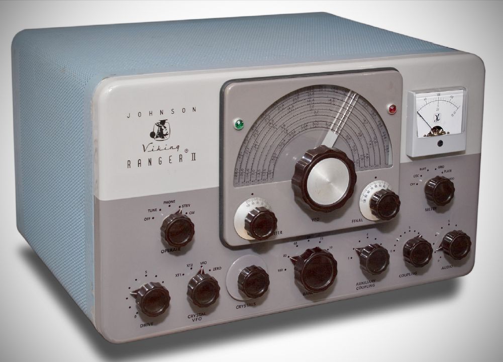
While the E.F. Johnson Viking Ranger (released in 1954) and the Ranger II (released in 1961) share the same core RF deck and architecture—both generating roughly 75 watts CW and 50 watts AM phone input using a single 6146 final amplifier—there are key differences between them.
The main practical and technical differences include:
1. Band Coverage (6M vs. 11M)
– The Original Ranger: Designed before the 11-meter band was reassigned away from amateur radio in 1958, the original covers 160, 80, 40, 20, 15, 11, and 10 meters.
– The Ranger II: Replaced the obsolete 11-meter position on the bandswitch with the 6-meter band. To achieve this, Johnson integrated an internal 6-meter doubler circuit powered by a 5763 vacuum tube.
2. Modulator Tubes
– The Original Ranger: Uses a pair of 1614 (or ruggedized metal 6L6) tubes in push-pull for the modulator circuit.
– The Ranger II: Shifted to a pair of 7027 beam power tetrades for the modulators. The 7027 tubes have higher plate voltage and dissipation .
⚠️ Note: The 7027s are shown correctly in the block diagram in the manual, but are still listed as 1614s in the schematic.
3. Keying System Refinements
– The Original Ranger: The earliest 1954 runs lacked factory timed-sequence keying, leaving them prone to noticeable key clicks or VFO chirps until Johnson added the sub-chassis circuitry as standard in late 1955.
– The Ranger II: Included clean grid-block, timed-sequence keying natively from day one, utilizing a 12AU7 keyer tube paired with a 6AL5 bias rectifier to smoothly sequence the stages.
4. Cosmetics, Cabinet, and Metering
– The Original Ranger: Features a classic mid-50s maroon/dark brown and tan-beige color scheme. It utilizes a smaller meter backlit with an amber glow.
– The Ranger II: Dressed down in a completely gray restyled cabinet to match Johnson’s later 1960s aesthetic. It also upgraded to a larger, square, unlit face meter that is significantly easier to read from across the operating desk.
Specifications
– Modes: AM, CW
– Frequency Coverage: 160, 80, 40, 20, 15, 10, and 6 meters.
– Power Output: 40 to 45 watts on Phone and 45 to 50 watts on CW.
– Antenna Matching: Features a built-in, bandswitched pi-network plate circuit designed to match nominal antenna impedances of 50 to 500 ohms. At frequencies above 7 MHz, its matching capabilities expand from roughly 25 to 2,000 ohms, allowing it to load a wide variety of unbalanced and random-length antennas.
– VFO: The VFO is patterned after the classic Johnson Model 122, employing a highly stable, series-tuned Colpitts circuit. It utilizes two primary tank circuits (1.75–2.0 MHz and 7.0–7.425 MHz) that are mechanically linked to the main bandswitch. For 6-meter operation, auxiliary capacitors are switched in to shift the VFO frequency to a harmonic range of 6.25 to 6.5 MHz.
The audio section provides robust, high-gain amplification designed for maximum communication punch. It features plate saturation limiting to prevent overmodulation and a tertiary feedback winding on the modulation transformer to improve stability and regulation.
– Crystal Operation: two crystal positions.
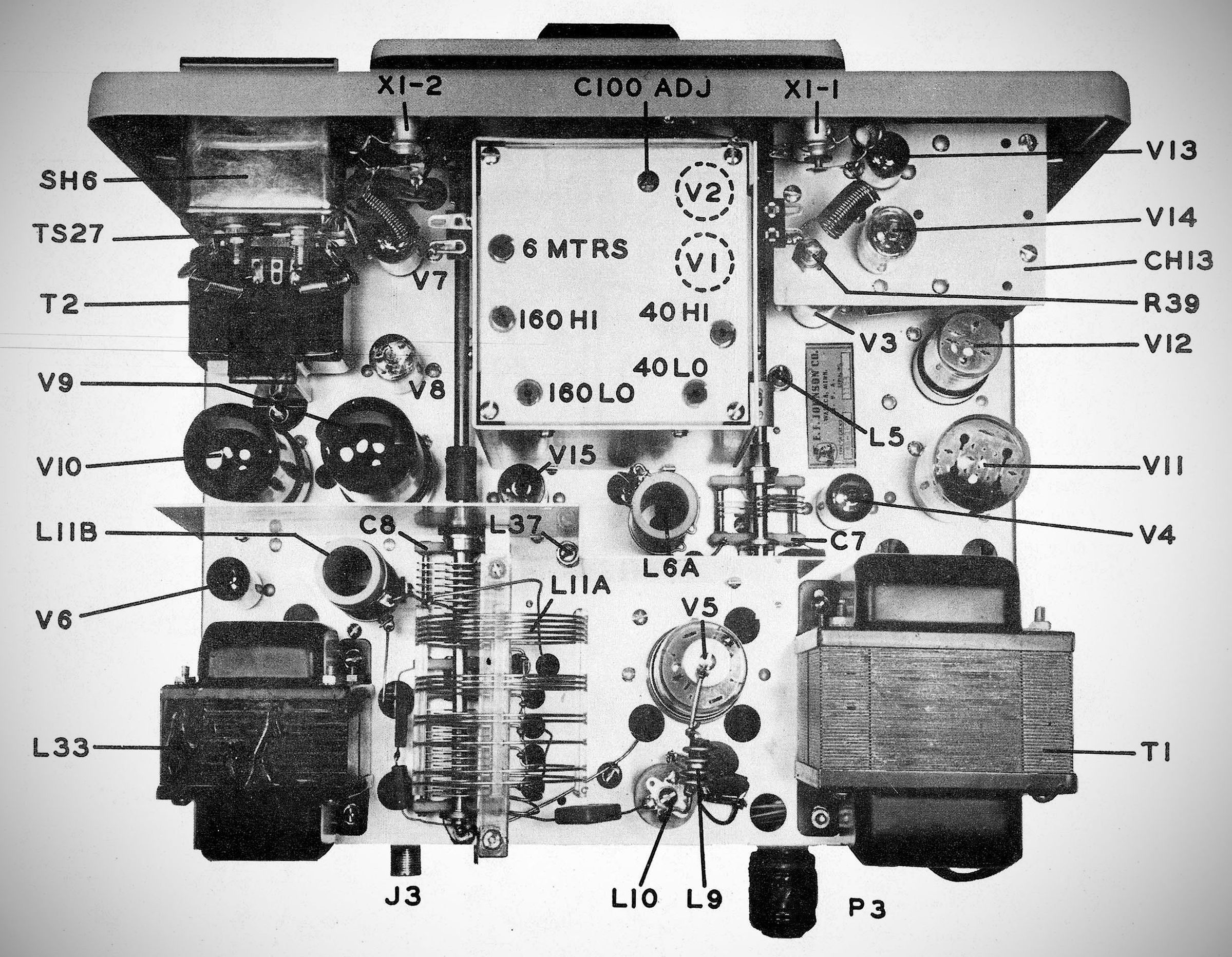
Tube Lineup (15 total)
6AU6 VFO Oscillator
6CL6 Crystal Oscillator / Frequency Multiplier / VFO Isolator
6CL6 Buffer-Multiplier
6146 Final RF Power Amplifier
6AQ5 Clamp Tube (Final Amplifier Screen Protection)
5763 6-Meter Doubler/Multiplier
12AX7 Dual-Triode Cascade 1st and 2nd Audio Speech Amplifiers
12AU7 Parallel-Connected Audio Driver
(2) 7027 Push-Pull Class AB1Modulators
5R4GY High-Voltage Rectifier
5V4G Low-Voltage Rectifier
0A2 VFO Voltage Regulator
12AU7 Timed Sequence Keyer
6AL5 Bias Rectifier
An integrated 9-pin auxiliary socket on the rear chassis provides filtered, TVI-suppressed hookups. Without requiring any internal modifications, the secondary winding of the Ranger II’s modulation transformer can be split to feed the grids of external high-power Class B modulators directly, while its internal power supply can even be tapped to run low-power auxiliary external station equipment.
KIt or wired.
References
Adding PTT. CQ, Feb 1957, p. 37.
Review. 73, Mar 1962, p. 61.
Use with Heath SB-10. CQ, May 1964, p. 41.