Note
Wired only.
QST, Aug 1962, p. 100.
QST, Aug 1963, p. 89.
QST, Mar 1964, p. 105.
QST, Jun 1964, p. 115. (save $100)
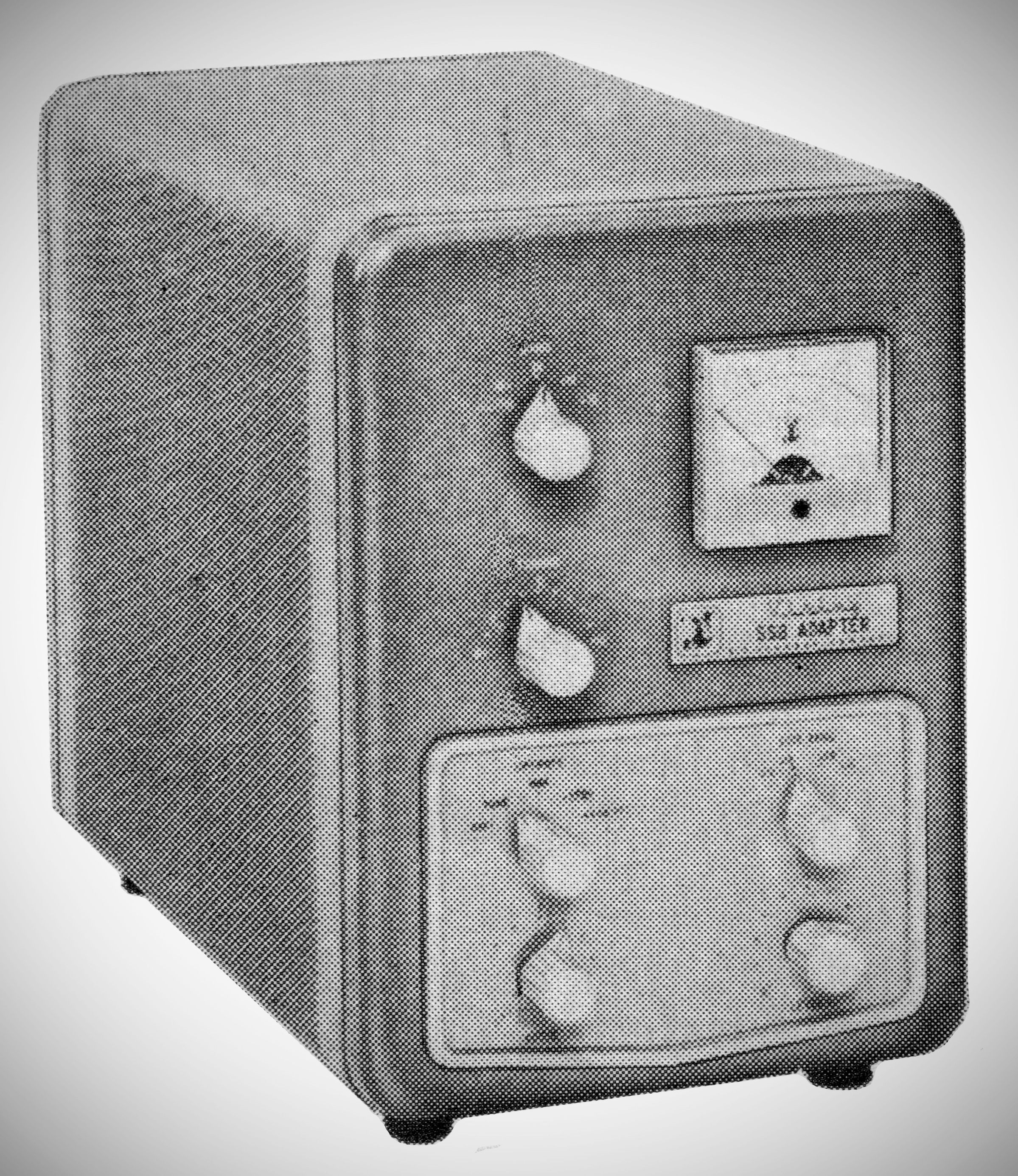
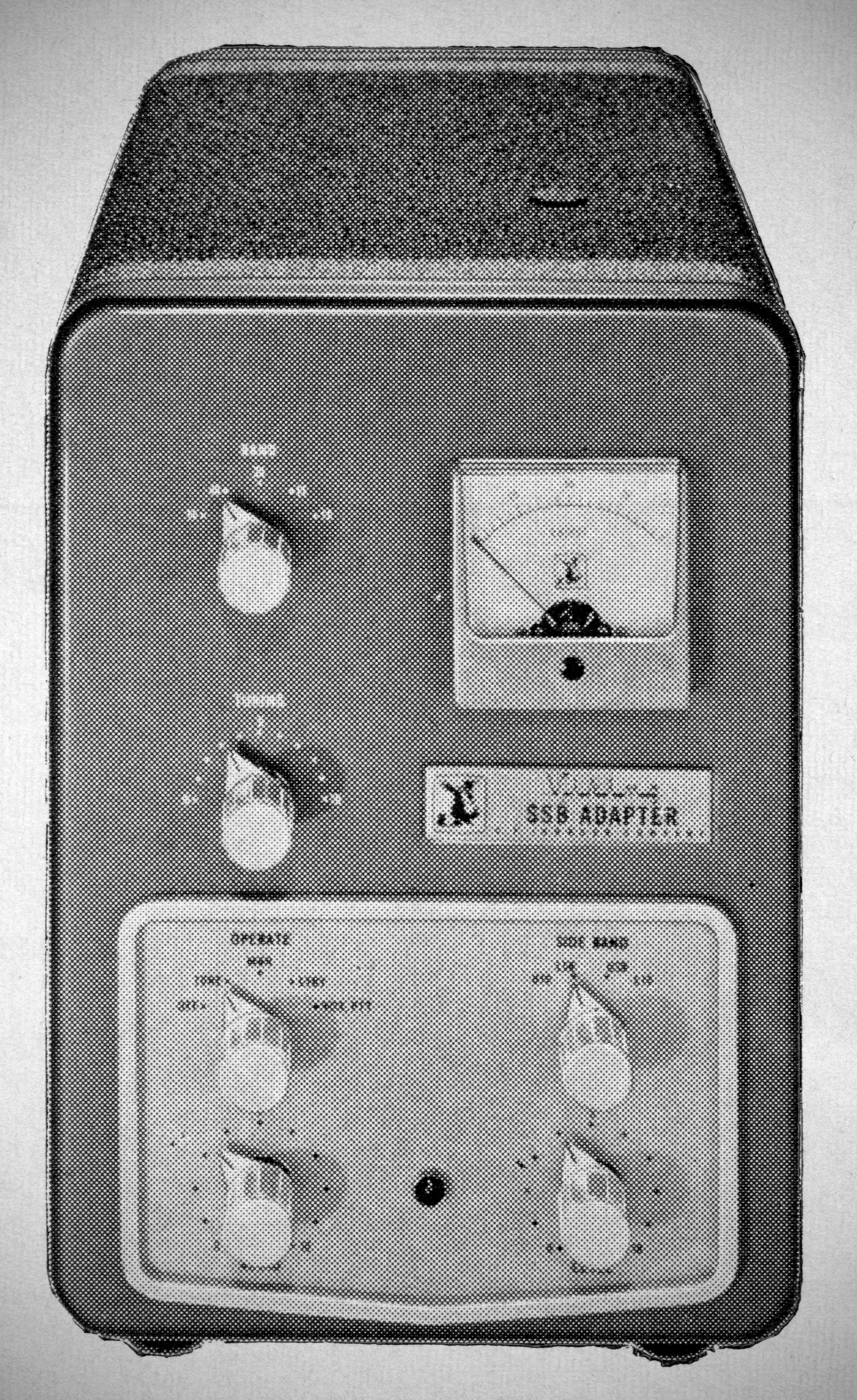
The E.F. Johnson Viking SSB Adapter (Model 240-305-2) is a filter-type single sideband generator designed to operate across the 80 through 10 meter amateur bands from 3.8 to 29.7 MHz.
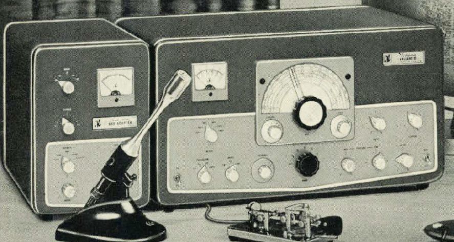
The unit delivers an RF output of approximately 2 watts across all bands and was specifically developed to work alongside the Johnson Valiant I and Valiant II transmitters, utilizing the transmitter's internal VFO for frequency control and its final two stages for power amplification.
The circuit layout features bandswitched, pretuned RF stages for simple band changing, with only the final amplifier tank circuit requiring manual tuning. Key circuitry elements include:
Mixers and Modulator: The 1st and 2nd mixer stages utilize 7360 beam-deflection tubes to achieve long-term stability and carrier suppression of at least 40 dB. A 7360 tube is also configured as a combined crystal oscillator and balanced modulator.
Filter: Carrier selection and sideband filtering rely on the same crystal filter design used in the high-end Viking Invader transmitter line.
Output Stage: The RF output stage employs a pi-network matching circuit fixed at a 50-ohm output impedance.
Audio & Switching: The unit features a two-stage audio amplifier optimized for high-impedance microphones, a built-in fixed audio tone oscillator for tune-up procedures, and versatile switching control for MANUAL, VOX, or Push-to-Talk (PTT) operation.
To ensure minimal interaction between stages, internal shielding is extensive: separate shielded sub-compartments enclose the balanced modulator-oscillator, filter assembly, multiplier, mixer, and final amplifier stages. Adequate cooling is maintained through perforated top, bottom, and side panels.
High voltage and filament power are supplied by an external, dedicated power supply built on a nickel-plated chassis with rubber mounting feet. The primary fuse, voltage regulator tubes, and rectifier tube are easily accessible on top of the power chassis.
Specifications
– Frequency Coverage:
3.8 to 4.0 MHz
7.2 to 7.3 MHz
14.2 to 14.35 MHz
21.25 to 21.45 MHz
28.5 to 29.7 MHz.
– RF Power Output: Approximately 2 watts into a 50-ohm load across all operational bands.
– Suppression Performance: Unwanted sideband suppression is 50 dB or better, carrier suppression is 45 dB or better, spurious output is down 50 dB or better, and intermodulation distortion products are better than 40 dB down.
Tube Lineup
– 7360: Carrier oscillator and balanced modulator
– 6AU6: Sideband RF amplifier
– 6EJ7: VFO frequency multiplier
– 7360: First balanced mixer
– 7360: Second balanced mixer
– 12BY7A: RF power amplifier
– 12AX7: First and second audio speech amplifiers
– 6U8A: Anti-trip amplifier and tune-up tone oscillator
– 12AT7: VOX amplifier and relay control amplifier
– 6AL5: VOX and anti-trip signal rectifiers
Power Supply & Voltage Regulation
– 5U4G: High-voltage full-wave rectifier
– 0A2: Voltage regulator
– 0B2: Voltage regulator
Power Requirements: 115 VAC, 50/60 Hz, 100 watts.
The companion power supply measures 3 1/8 inches wide, 6.5/8 inches high, and 7.5 inches deep, weighing 10 pounds.