Note
QST, Jun 1962, p. 99.
QST, Mar 1964, p. 105.
QST, Apr 1965 p. 5.
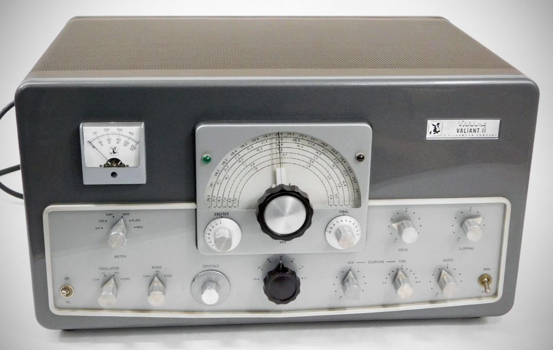
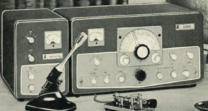
Dressed up in Johnson's new style, the Valiant II shared most operating features and specifications with the original Valiant transmitter. It added rear panel connections for RF and control circuits when used with a sideband adapter. The Johnson Sideband Adapter was a filter-type generator that worked on 80 through 10 meters. Its 2-watt output would drive a Valiant or Valiant II to full power. The adapter's power supply was a separate unit and could be mounted remotely.
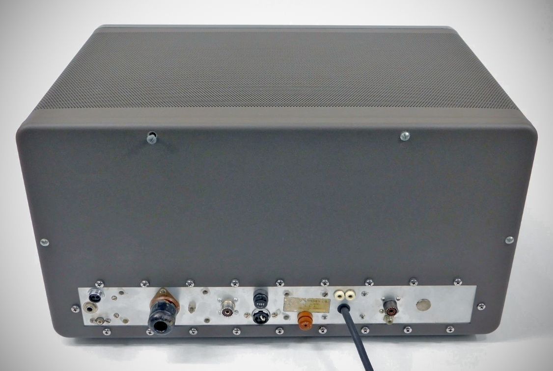
Unlike its predecessor, the Valiant II includes rear-panel connections specifically for plug-in SSB operation without requiring internal modifications. This includes rear coax fittings for VFO output and SSB input, alongside a 5-pin control receptacle to interface remote bias control and VFO keying with an SSB adapter's VOX circuit.
Incorporates a high-gain push-to-talk audio system compatible with high-impedance crystal or dynamic microphones, a low-pass audio filter, and low-level audio clipping to prevent overmodulation while improving signal punch and intelligibility.
Built with grid-block timed-sequence keying for clean CW operation and comprehensive shielding and filtering for TVI suppression.
Equipped with a rear 9-pin accessory socket that brings out filtered control and audio lines. This allows the unit to drive high-power kilowatt amplifiers, serve as a modulator, or supply filament and plate power to external VHF equipment.
– Frequency Coverage: Features complete front-panel bandswitching covering the 160, 80, 40, 20, 15, and 10 meter amateur bands.
– Power Ratings:
275 watts input on CW
200 watts input on AM
275 watts PEP input on SSB when used with an auxiliary exciter or the Viking SSB Adapter
– Frequency Control: Driven by a built-in, differentially temperature-compensated variable frequency oscillator (VFO) operating in the 1.75–2.0 MHz and 7.0–7.45 MHz ranges, designed for high stability required during SSB operations.
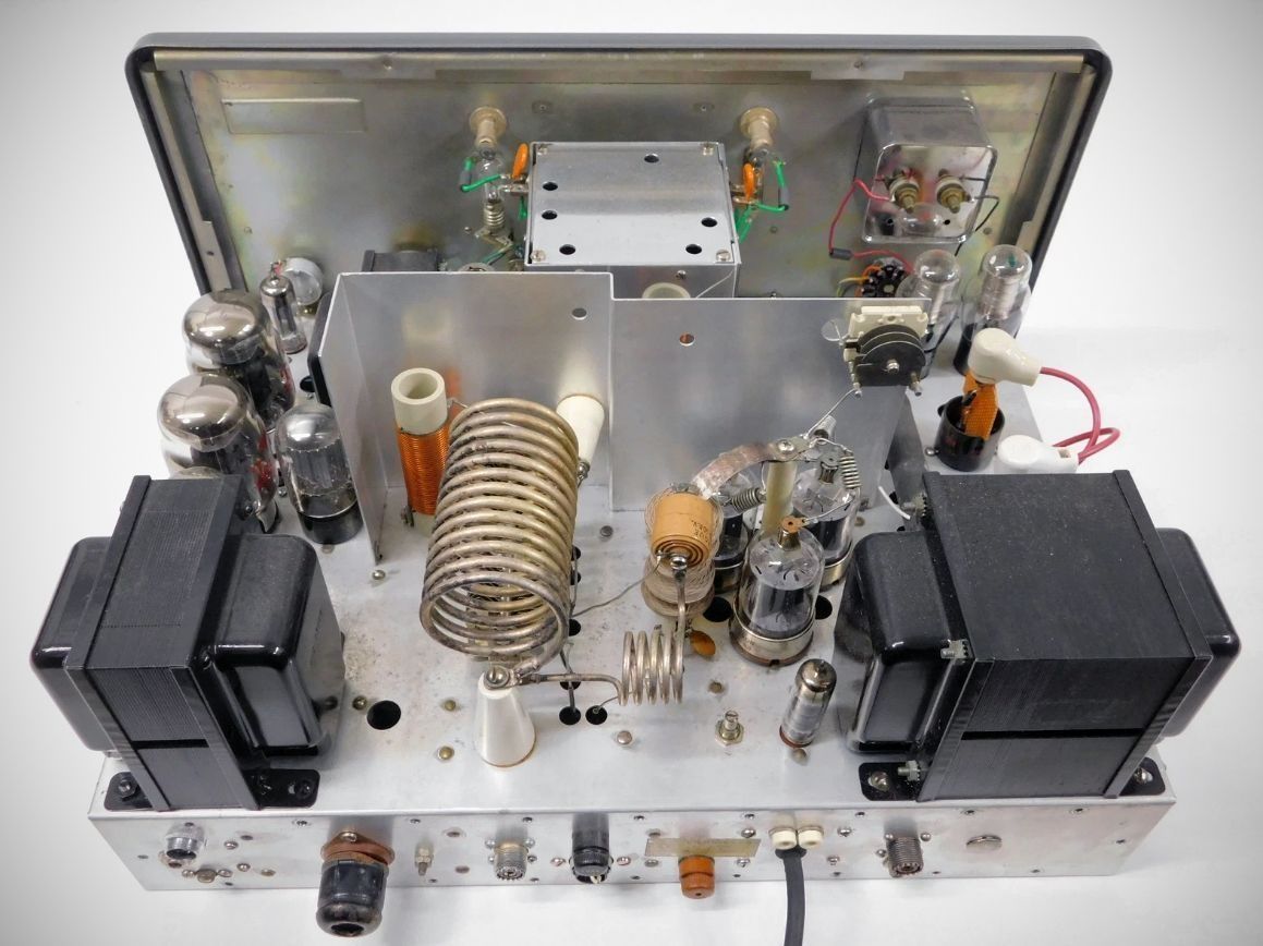
– Output Tank Circuit: Utilizes a high-efficiency pi-network matching circuit capable of handling antenna loads from 50 to 600 ohms and tuning out substantial reactance, featuring a silver-plated final tank coil.
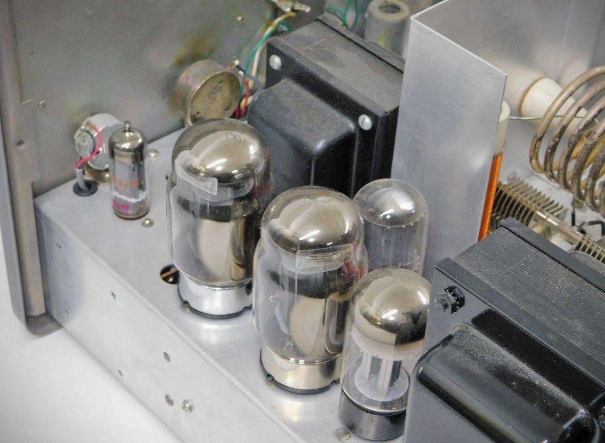
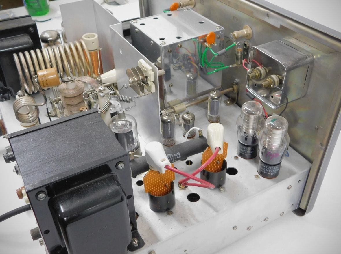
Tube Lineup (21 total)
– 6AU6: Variable Frequency Oscillator (VFO)
– 0A2: Voltage Regulator for the VFO screen
– 6CL6: Crystal Oscillator / Buffer
– 5763: Frequency Multiplier / Driver
– 12AU7: Keyer tube
– (3) 6146): Parallel RF Power Amplifiers
– 6AQ5: Screen Clamper
– 12AX7: Dual Triode Speech Amplifier
– 6AL5: Diode Audio Clipper
– 6C4: Third Audio Amplifier
– 12AU7: Audio Driver
– (2) 6146: Push-Pull Modulators
– (2) 0C3 / VR-105): Voltage Regulators for final amplifier/modulator screens
– (2) 866A: High Voltage Rectifiers
– 5V4G: Low Voltage Rectifier
– 6BY5GA: Bias Voltage Rectifier
Power requirements
105 to 125 VAC, 50/60 Hx
Standby Power Consumption: 185 watts.
Full CW Load Power Consumption: 560 watts (key down, fully loaded).
Full AM Phone Power Consumption: 560 watts (fully loaded at average speech modulation peaks).
Kit Version (Cat. No. 240-105-1)
Wired & Tested (Cat. No. 240-105-2)