Note
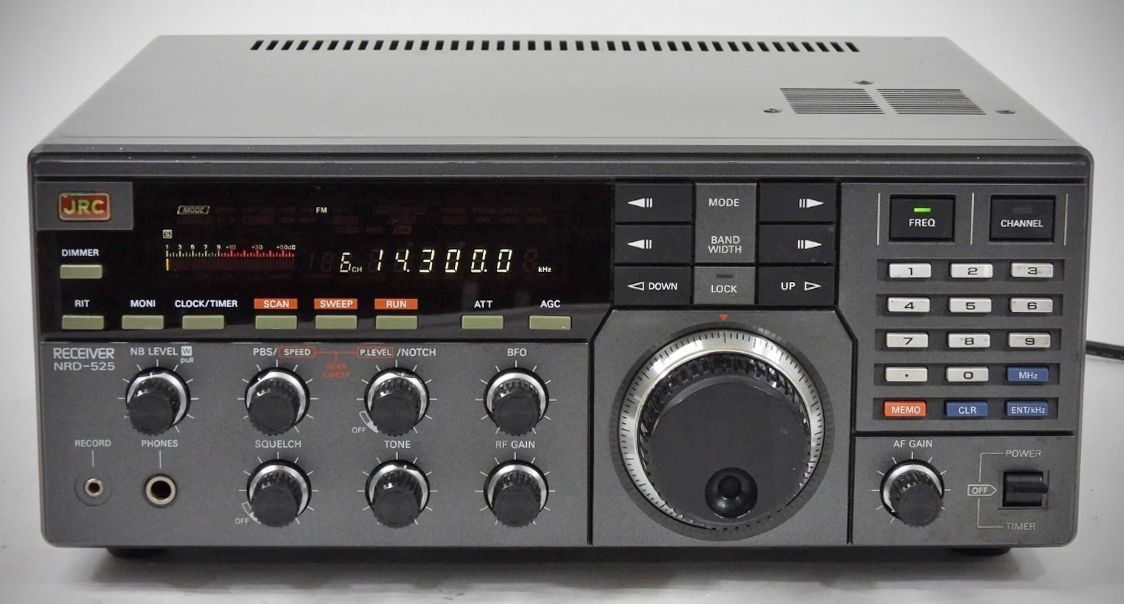
The NRD-525 is a professional-grade communications receiver that utilizes a double superheterodyne system. It features a wide receiving frequency range from 0.09 MHz to 34 MHz in its standard configuration, which can be expanded into the VHF and UHF bands (up to 456 MHz) with the addition of an optional converter.
Features
– Double Superheterodyne System: Utilizes a sophisticated receiving system for high-quality signal processing.
– Pass Band Shift (PBS): Provides a variation range of ±1 kHz or more to help eliminate interference.
– IF Notch Filter: Offers attenuation of -30 dB or more to cut out specific interfering tones.
– Noise Blanker: Includes dedicated circuitry to reduce pulse-type noise.
– Frequency Stability: Maintains a stability of ±3 PPM for precise tuning.
– 200 Memory Channels: Allows for extensive storage of frequencies and modes.
– RIT (Receiver Incremental Tuning): Features a variation range of up to ±5 kHz.
– BFO Variation: Provides a range of 455 kHz±2 kHz or more.
– Clock and Timer: Built-in functions for time tracking and automated operation.
Specifications
Receiving frequency range:
0.09-34 MHz
34-60 MHz (With the optional V.UHF converter CMK-165)
114-174 MHz (With the optional V.UHF converter CMK-165)
423-456 MHz (With the optional V.UHF converter CMK-165)
Modes: RTTY, CW, SSB (USB, LSB), AM, FM, FAX
Memory channel: 200 channels
Receiving system: Double superheterodyne
1st IF: 70.45399-70.453MHz
2nd IF: 455 kHz
Sensitivity
FREQUENCY CW/SSB AM FM
0.09-1.6MHz 5.0μV 15μV —
1.6-34MHz 0.5μV 2μV 0.7μV
34-60MHz 1.0μV 3μV 1.5µV
114-174MHz 1.0μV 3μV 1.5µV
425-445MHz 1.0μV 3μV 1.5µV
S/N=10dB, AF output =100mW bandwidth=INTER
Modulation =400Hz, 30% (during AM measurement)
NQL=20dB (during FM measurement)
Antenna impedance =50Ω
Selectivity
Bandwidth 6dB 60dB
AUX 12kHz or more
WIDE 4kHz or more 10kHz or less
INTER 2kHz or more 6kHz or less
NARR 1kHz or more 3kHz or less
FM 12kHz or more —
Image frequency rejection ratio: 70 dB or more
Intermediate frequency rejection ratio: 70 dB or more
Frequency stability: ±3 PPM
Dynamic range: 100 dB or more (with 500Hz IF selectivity)
PBS variation range: ±1 kHz or more
Notch attenuation: –30 dB or more
BFO variation range: 455 kHz±2 kHz or more
RIT variation range: ±5 kHz, maximum
Nominal Antenna impedance:
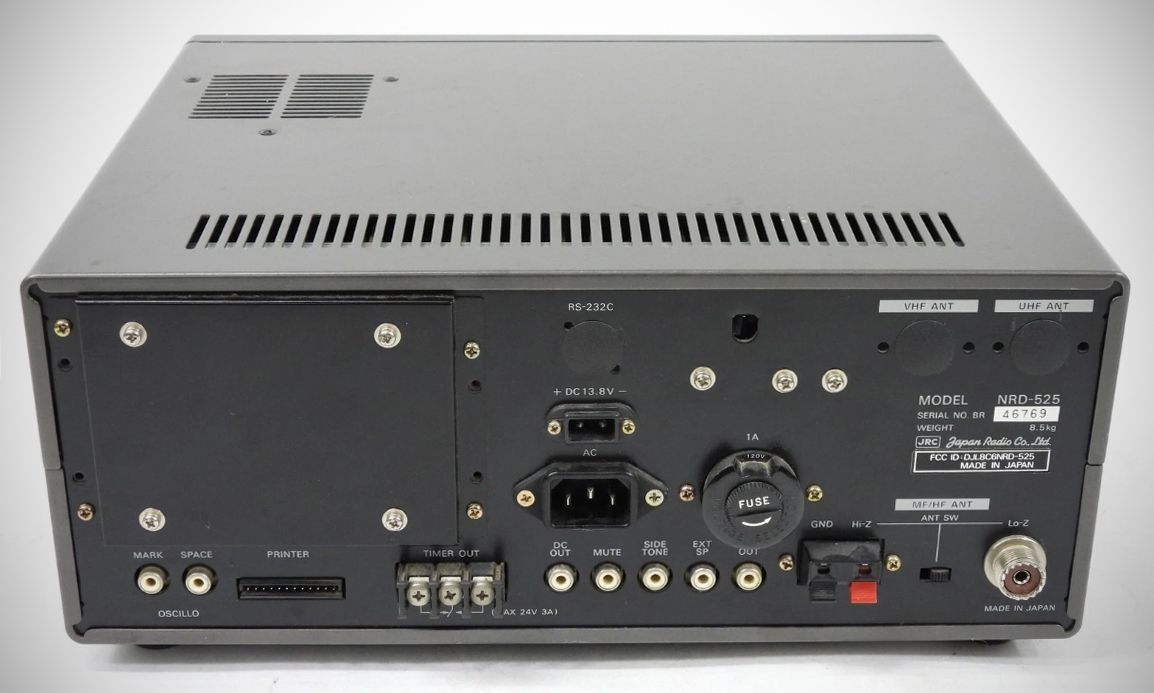
0.09-34MHz: 50Ω (Lo-Z terminal), 600Ω (Hi-Z terminal)
34-60MHz: 50Ω (VHF terminal)
114-174MHz: 50Ω (VHF terminal)
23-456MHz: 50Ω (UHF terminal)
AF output
Speaker output: 0.5 W or more (at 4Ω load and 10% distortion)
Line output: 1 mW or more (at 600Ω load and 10% distortion)
Recording output: 1 mW or more
Antenna input attenuation
Approx. 20 dB for HF
Approx. 10 dB for VHF/UHF
AGC characteristic: Change of output is 10 dB or less when the antenna input changes by 3μV to 100 mV.
Power source
100/120/220/240 V AC±10% Max. 35 VA
12-16V DC (standard 13.8 V) Max. 25 W