Note
QST, Dec 1976, p. 106.
QST, Nov 1977, p. 183.
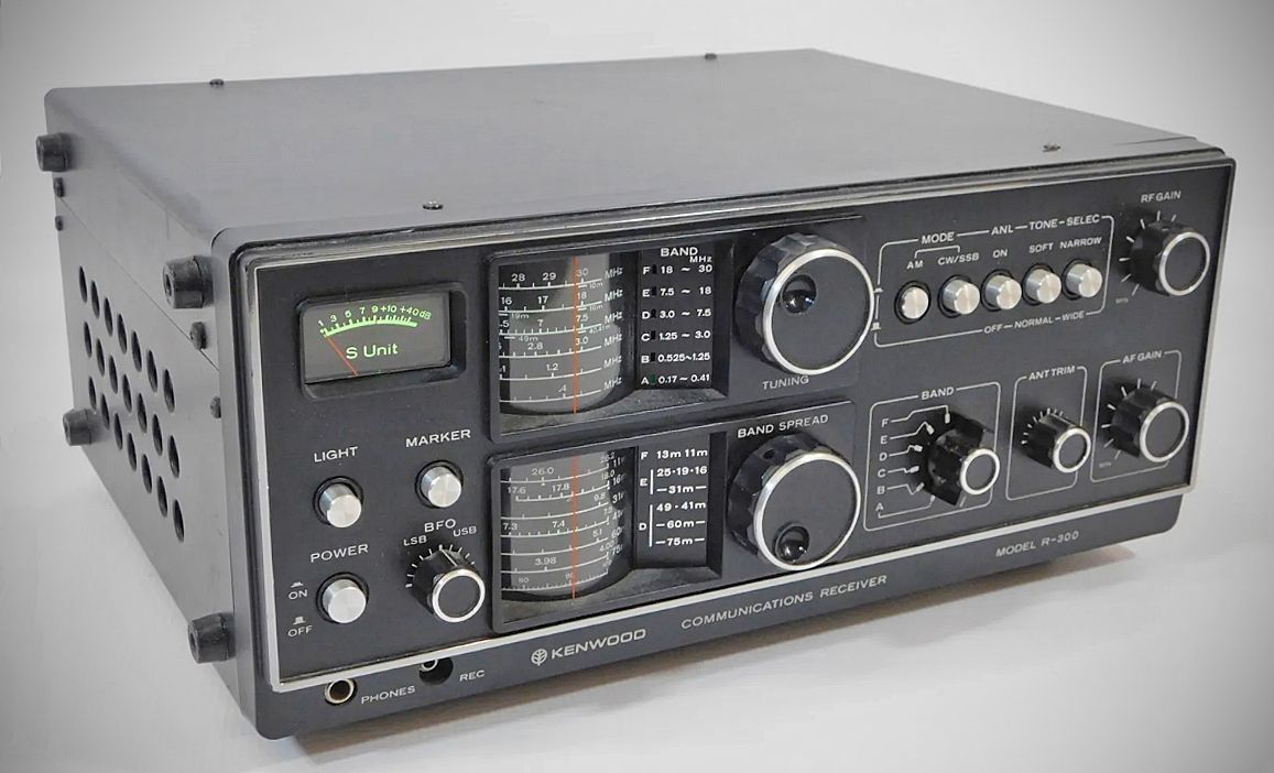
The Kenwood R-300 is a solid-state general coverage communications receiver manufactured by Trio-Kenwood Communications. Designed as an accessible, moderately priced option, it targeted shortwave listeners (SWLs) as well as radio amateurs looking for a secondary receiver.
Noted for offering a full feature set—including a crystal calibrator and smooth, backlash-free tuning controls—at a budget-friendly price point. Sensitivity was reported as solid across most bands, though adding a preamplifier was typically recommended for serious monitoring on the 10-meter band.
Features
– Covers 170 kHz to 30 MHz continuously (with a minor gap from 410 kHz to 525 kHz) across six selectable bands.
– Sub-broadcast / VLF reception capability, making it popular for monitoring VLF weather, information, and CW stations around 170 kHz.
– Tuning Architecture: Employs a classic analog LC tuning design (no phase-locked loops or digital synthesis). Uses two drum-style tuning dials with "rapid-twirl" indentations for the main tuning and bandspread controls. Bandspread tuning covers three of the six ranges (starting from 3.0 MHz) with 20 kHz scale increments. Features a green semaphore indicator next to the active tuning range.
– Modes: AM, CW, and Single Sideband (SSB).
– Controls: BFO control for fine-tuning SSB/CW, RF gain, Audio gain, antenna trimmer, noise limiter (ANL), tone control, and panel illumination switch.
– Built-in Calibrator: Includes a crystal calibrator to accurately zero-beat and align the main tuning and bandspread scales.
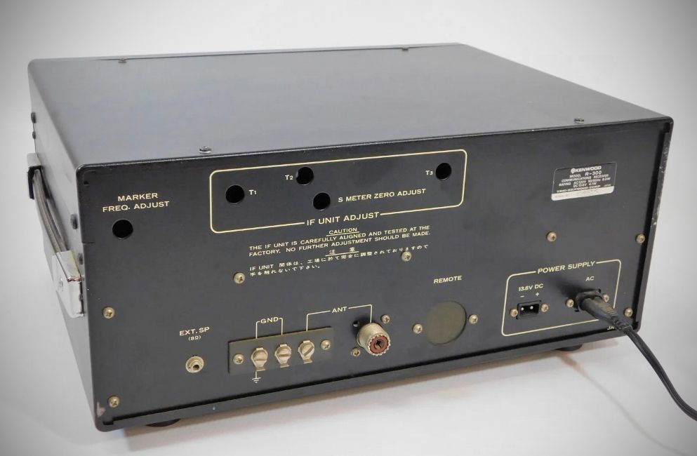
– Analog S-meter with a rear-panel zero adjustment.
Specifications
Frequency coverage: 170 kHz – 30 MHz
Band Spread Range (Varies depending on destination area)
Short Wave Bands:
– 75 m: 3.82 – 4.0 MHz
– 60 m: 4.75 – 5.1 MHz
– 49 m: 5.9 – 6.2 MHz
– 41 m: 7.0 – 7.5 MHz
– 31 m: 9.4 – 9.8 MHz
– 25 m: 11.7 – 12.0 MHz
– 19 m: 15.0 – 15.5 MHz
– 16 m: 17.6 – 18.0 MHz
– 13 m: 21.4 – 21.8 MHz
– 11 m: 25.6 – 26.2 MHz
Amateur Bands:
– 80 m & 75 m: 3.5 – 4.0 MHz
– 40 m: 7.0 – 7.5 MHz
– 20 m: 14.0 – 14.6 MHz
– 15 m: 21.0 – 21.5 MHz
– 10 m: 28.0 – 30.0 MHz
Sensitivity (Measured at (S+N)/N = 10 dB at 50 mW / 8 Ω output)
Modes: AM, SSB, CW
Band A (280 kHz): AM: Better than 1 µV | SSB: Better than 0.3 µV
Band B (900 kHz): AM: Better than 1 µV | SSB: Better than 0.3 µV
Band C (2.0 MHz): AM: Better than 1 µV | SSB: Better than 0.3 µV
Band D (5.0 MHz): AM: Better than 1.5 µV | SSB: Better than 0.5 µV
Band E (12.0 MHz): AM: Better than 1.5 µV | SSB: Better than 0.5 µV
Band F (24.0 MHz): AM: Better than 1 µV | SSB: Better than 0.3 µV
– Selectivity:
Narrow: More than 2.5 kHz at -6 dB | Less than 12 kHz at -60 dB
Wide: More than 5 kHz at -6 dB | Less than 17 kHz at -60 dB
– IF Rejection:
Band A (280 kHz): Better than 50 dB
Band B (900 kHz): Better than 60 dB
Bands C – F (2.0 – 24.0 MHz): Better than 70 dB
– Image Ratio:
Band A (280 kHz): Better than 65 dB
Band B (900 kHz): Better than 50 dB
Band C (2.0 MHz): Better than 45 dB
Band D (5.0 MHz): Better than 40 dB
Band E (12.0 MHz): Better than 25 dB
Band F (24.0 MHz): Better than 40 dB
– Audio Output: 1.5 W at 8 Ω load (10% distortion)
– Antenna Impedance: 50 ~ 75 Ω
– Audio Output Impedance: 4 to 8 Ω
– Semiconductor Complement: 4 FETs, 21 Transistors, 24 Diodes
Power Requirements:
AC 100 / 117 / 220 / 240 V
DC 12 – 16 V (13.8 V as reference)
Power Consumption:
AC (100/117/220/240 V): 8 W
DC (13.8 V): 4.1 W
DC (13.8 V with LIGHT switch ON): 6.9 W
Power Options:
Operates on AC mains, external DC, or internal batteries, making it suitable for portable/field use.