Note
QST, Oct 1970 p. 5.
QST, Sep 1973, inside front cover. (R-599A)
QST, Nov 1975, p. 143. (R-599D)
QST, Feb 1977, p. 103.
QST, Dec 1978, p. 6. (Additional detail)
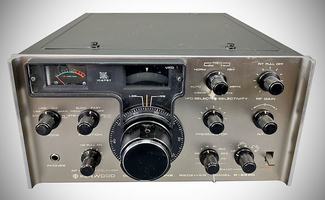
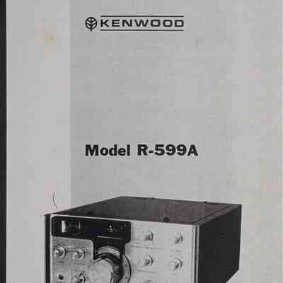
The Kenwood R-599 (marketed under the Trio brand in Japan as the JR-599) is a solid-state amateur band communications receiver introduced in 1970. Nicknamed the "Twins" alongside its matching transmitter, the T-599 (TX-599), it represented a major transition period in amateur radio design—shifting away from vacuum tube circuits toward solid-state architecture and modular PCB construction.
Variants:
R-599A: Introduced in 1973 adding an illuminated main VFO dial, a improved tuning rate gear mechanism, and an integrated noise blanker (NB) circuit.
R-599D / R-599S: Introduced in 1975. Subsequent cosmetic/trim variants produced for different regional markets (including variations in faceplate finish and panel accents).
Key Features
– Frequency Coverage:
Standard HF amateur bands: 1.8–2.3 MHz, 3.5–4.0 MHz, 7.0–7.5 MHz, 14.0–14.5 MHz, 21.0–21.5 MHz, and 28.0–29.7 MHz (split across three 500 kHz segments).
Additional coverage includes the 27 MHz CB band (26.8–27.4 MHz) and 10.0 MHz WWV time/frequency signals.
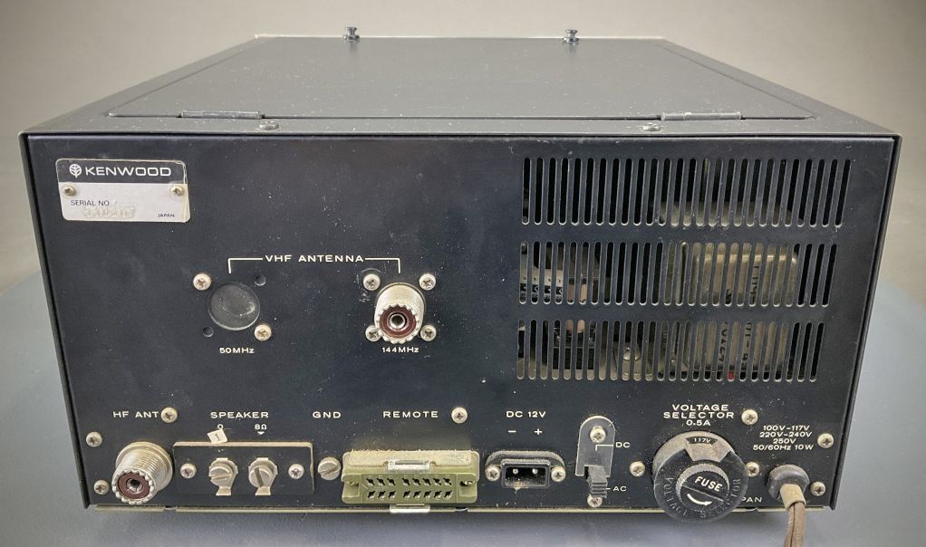
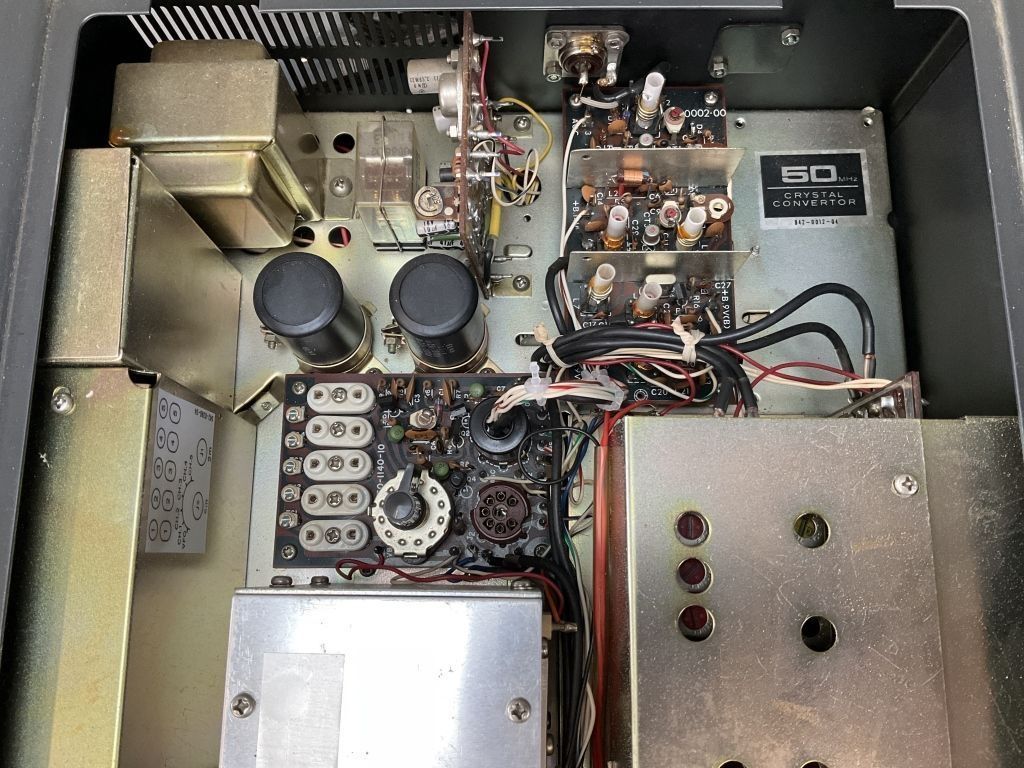
Extended VHF coverage on 6 meters (50.0–53.4 MHz) and 2 meters (144.0–147.4 MHz) is supported via optional internal converter boards.
– Operating Modes: LSB, USB, CW, AM, and FM.
– Architecture: Double-superheterodyne architecture for HF/CB bands and triple-superheterodyne for VHF bands with optional converters.
– Design & Construction: Modular solid-state design utilizing removable, socketed circuit boards. The semiconductor complement includes 30 transistors, 51 diodes, 2 Zener diodes, 1 variable capacitance diode, and 2 integrated circuits.
Operating Capabilities
– Direct Frequency Readout: Features an analog sub-dial (25 kHz graduations) and a main dial scale providing 1 kHz tuning resolution.
– Selectivity & Filters: Equipped with dedicated crystal filters for SSB, CW, AM, and FM modes, selectable manually or set to automatically match the selected mode.
– Receiver Incremental Tuning (RIT): Provides \pm 2\text{ kHz} fine-tuning off the main dial setting, primary for split-frequency transceive operation with the T-599A.
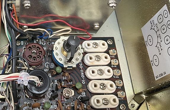
– Fixed Channel Operation: Includes internal switching and crystal sockets for up to five crystal-controlled spot frequencies within any selected band.
– Transceive Interfacing: Connects to the T-599A(D) transmitter using a 16-pin REMOTE interconnect cable to enable flexible VFO switching (master/slave VFO, cross-band, or split-frequency transceiving) and shared sidetone/calibration features.
– Signal Processing Controls: Built-in impulse Noise Blanker (NB), adjustable squelch threshold, selectable AGC (Fast, Slow, or Off), 25\text{ kHz} crystal calibrator, and an S-meter calibrated up to +80\text{ dB} over S9.
Specificstions
Frequency Range:
– 1.8 MHz Band: 1.8 to 2.3 MHz
– 3.5 MHz Band: 3.5 to 4.0 MHz
– 7.0 MHz Band: 7.0 to 7.5 MHz
– 14.0 MHz Band: 14.0 to 14.5 MHz
– 21.0 MHz Band: 21.0 to 21.5 MHz
– 28.0 MHz Band: 28.0 to 28.5 MHz
– 28.5 MHz Band: 28.5 to 29.1 MHz
– 29.1 MHz Band: 29.1 to 29.7 MHz
– CB Band: 26.8 to 27.4 MHz
– 50.0 MHz Band: 50.0 to 53.4 MHz (with accessory converter)
– 144.0 MHz Band: 144.0 to 147.4 MHz (with accessory converter)
– WWV: 10.0 MHz
– Modes: LSB, USB, CW, AM, and FM
– Audio Output Impedance: 4 to 16 ohms (for speaker or headphones)
– Audio Output: More than 1 watt (with less than 10% distortion) into an 8 ohm load
– Antenna Input Impedance: 50 to 75 ohms (unbalanced)
– Frequency Stability:
Within 100 Hz during any 30-minute period after warmup
Within ±2 kHz during the first hour after warmup
– Calibration Accuracy: Within 2 kHz across the frequency range after calibration at zero
– Backlash: Not more than 400 Hz when the dial is advanced from 0 to 600 and returned to zero
– Frequency Readout: Complete to 1 kHz calibrations on the dial scale
– Image Ratio: Better than 50 dB down when compared to 1 µV
– First IF: 8.295 MHz to 8.895 MHz
– Second IF: 3.395 MHz
– IF Interference: Better than 50 dB down when compared to 1 µV
– Sensitivity (All with a 10 dB (S+N)/N ratio) :
SSB: 1.8 through 28 MHz Bands: Better than 0.5 µV
CB Band: Better than 0.5 µV
50 MHz Band: Better than 1.0 µV (with accessory converter)
144 MHz Band: Better than 1.0 µV (with accessory converter)
WWV Band: Better than 0.5 µV
AM: 1.8 through 28 MHz Bands: Better than 3.0 µV
CB Band: Better than 3.0 µV
50 MHz Band: Better than 6.0 µV (with accessory converter)
144 MHz Band: Better than 6.0 µV (with accessory converter)
WWV Band: Better than 3.0 µV
– Selectivity:
SSB: Better than 2.4 kHz bandwidth (-6 dB); better than 4.4 kHz bandwidth (-60 dB)
CW: Better than 500 Hz bandwidth (-6 dB); better than 1.5 kHz bandwidth (-60 dB)
AM: Better than 5 kHz bandwidth (-6 dB); better than 12 kHz bandwidth (-60 dB)
FM: Better than 20 kHz bandwidth (-6 dB); better than 120 kHz bandwidth (-40 dB)
– AGC: Selectable automatic gain control for Fast, Slow, or OFF
– Squelch: Built-in squelch
– VFO Versatility: Versatile cross-channel operation with matching T-599A transmitter
– Fixed Frequency Operation: Built-in fixed frequency oscillator for single-channel operation
– Calibrator: Built-in 25 kHz crystal oscillator
– RIT (Receiver Incremental Tuning): Variable receive frequency ±2 kHz or more
– Metering: Built-in S-meter (S1 through S9 to +80 dB over)
– Semiconductor Complement:
2 ICs
30 Transistors
51 Diodes
2 Zener Diodes
1 Variable Capacity Diode
Accessories include the CC-29A 2 meter converter, the CC-69 6 meter converter, and the FM-599A FM filter.
Power Requirements:
AC: 100 / 117 / 220 / 240 VAC, 50/60 Hz
DC: 12 to 15 VDC (operates directly from a 12 VDC power source)
Power Consumption: Less than 15 watts