Note
QST, Feb 1982, back cover.
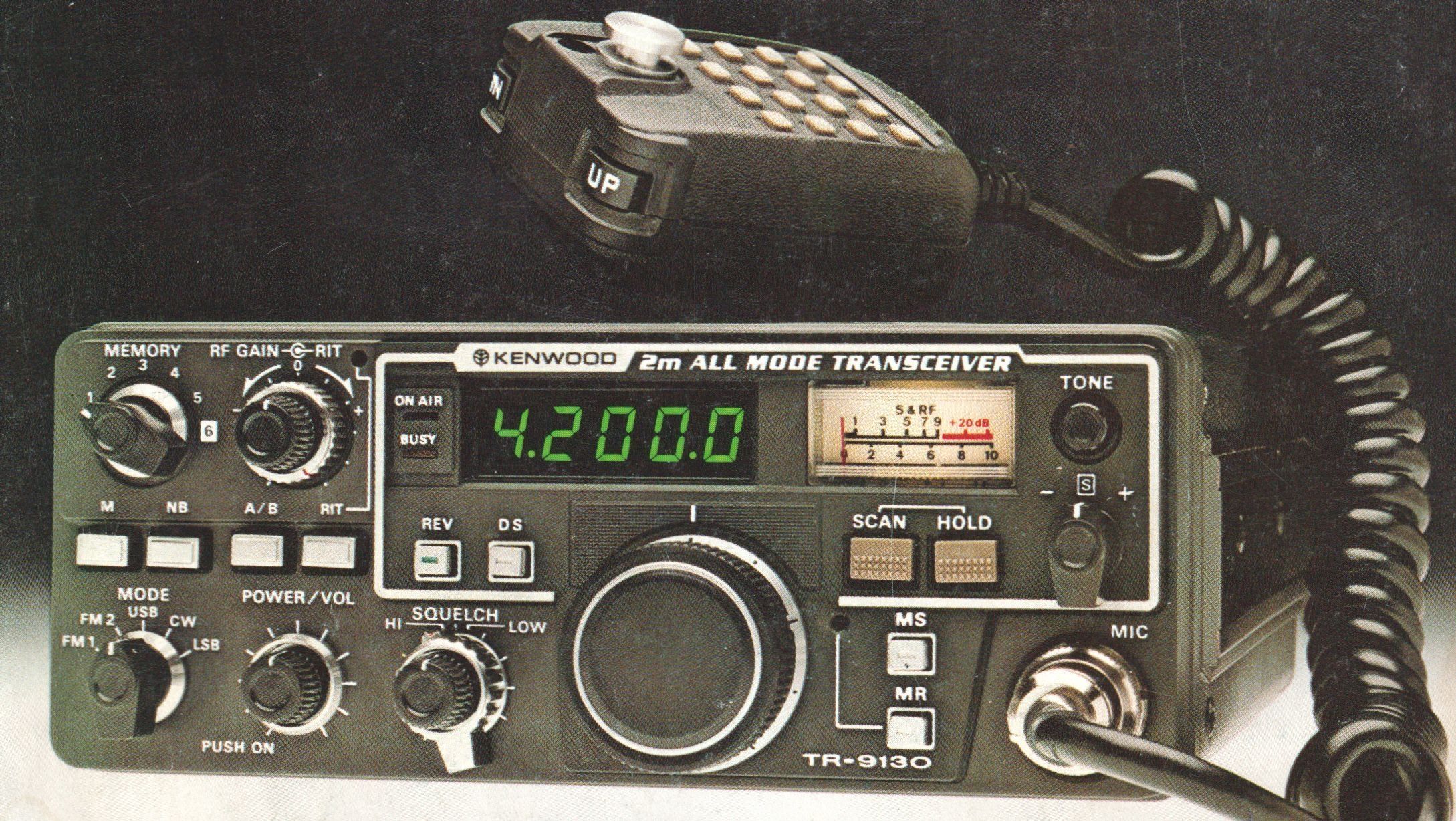
The Kenwood TR-9130 is a 2-meter multi-mode amateur radio transceiver designed primarily for mobile operation, though it is also fully featured for use as a fixed base station.
Features
– Mulit-Mode Capabilities: The radio supports FM, SSB (USB/LSB), and CW operations within the 144.0 to 146.0 MHz frequency range.
– Digital 2-VFO System: It features a click-type, endless rotary digital tuning dial that acts as a dual-VFO system (VFO-A and VFO-B).
– Selectable Frequency Steps: Depending on the selected mode and the position of the DS (Digital Step) switch , the tuning resolution can be set to 100 Hz, 1 kHz, 5 kHz, 12.5 kHz, or 25 kHz .
– Frequency Display: Operating frequencies are shown via a bright 5-digit LED display (or 4 digits, depending on the frequency step).
– RF Power Output: Features an RF Power HI/LOW switch. In FM and CW modes, the high power setting delivers a minimum of 25 Watts , while the low power mode outputs approximately 5 Watts. In SSB mode, the radio transmits at high power regardless of the switch position.
– Repeater Offsets: A dedicated TX OFFSET switch shifts the transmit frequency for standard repeater access. A REV (Reverse) switch allows operators to instantly reverse the transmit and receive frequencies to check if a station can be heard on the repeater's input frequency.
– Tone Signal: Includes a built-in 1,750 Hz repeater control tone burst circuit, activated via the front-panel TONE switch.
– CW Features: Built-in CW break-in and side-tone circuitry are fully incorporated. The transmitter frequency is also continuously variable in SSB/CW modes, making it capable of tracking satellite communications (such as Oscar).
– Receiver Circuit Architecture: Employs a double conversion superheterodyne design for FM, and a single conversion superheterodyne configuration for SSB and CW modes.
– SSB Squelch: Features a specialized SSB squelch circuit to provide quiet, comfortable standby operation during periods of no signal, matching the convenience typically found in FM squelch systems.
– Signal Metering: The analog S-meter doubles as a receive signal strength indicator and a transmit relative RF output meter.
– Interference Rejection: Includes an integrated Noise Blanker (NB) switch to eliminate pulsating ignition noise, automatic AGC, and an adjustable RF Gain control.
– 6 Memory Channels: The unit provides 6 memory slots. Channel 6 ( CH6 ) can store two distinct, independent frequencies (split transmit and receive) to facilitate "odd-split" non-standard repeater operation.
– Memory Scan (MS): Includes scanning operations that can scan the entire VFO band or selectively scan *only* the frequencies saved in the memory channels.
– Microcomputer Back-up: To ensure programmed memories and VFO frequencies are not lost when the main power is switched off, the TR-9130 features a low-drain memory backup system. Operators can install an internal 9V Ni-Cd battery or connect external back-up power (such as Kenwood's BC-1 charger) to retain memory function when disconnected from a primary 12V supply.
Specifications
– Semiconductors: 12 ICs, 15 FETs, 105 Transistors, 126 Diodes
– Frequency Range: 144.0 to 146.0 MHz
– Frequency Synthesizer: Digital control, phase locked VCO
– Modes: SSB, FM, CW
– RF Output Power (at 13.8V DC, 50 ohm load):
HI (SSB, FM, CW): 25W minimum.
LOW (FM, CW): 5W approximately
– Modulation:
FM: Variable reactance direct shift
SSB: Balanced modulation
– Tone Frequency: 1,750 Hz
– Frequency Tolerance: SSB, CW: Less than $\pm10 \times 10^{-6}$
– FM: Less than $\pm20 \times 10^{-6}$
– Spurious Radiation:
HI power: Less than $-60\text{dB}$
LOW power: Less than $-53\text{dB}$
– Carrier Suppression: Better than 40dB
– Unwanted Sideband Suppression: Better than 40dB
– Maximum Frequency Deviation (FM): $\pm5\text{ kHz}$
– Microphone: Dynamic microphone with PTT switch ($500\ \Omega$)
– Receiver Circuitry: FM: Double conversion superheterodyne
– SSB, CW: Single conversion superheterodyne
– Intermediate Frequency (IF): 1st IF: 10.695 MHz
– 2nd IF (FM): 455 kHz
– Receiver Sensitivity: FM: Better than 0.5 uV for 30dB S/N; better than 0.2uV for 12dB SINAD
– SSB, CW: 0.2 uV for 10dB S/N
– Receiver Selectivity: FM: More than 14 kHz (at –6 dB); less than 30 kHz (at –60 dB)
– SSB, CW: More than 2.2 kHz (at –6 dB); less than 4.8 kHz (at –60 dB)
– Spurious Interference: Better than 70dB
– Squelch Sensitivity: 0.16 uV (Threshold)
– Auto Scan Stop Level: Less than 0.2 uV (Threshold)
– Audio Output: More than 2.0 Watts across an 8 ohm load (at 10% distortion)
Power Requirement: 13.8 VDC ±15%
Current Drain:
Receive mode (no input signal): 0.7A
Transmit mode (HI power, approx.): 6.0A
Transmit mode (LOW power, approx.): 3.5A
Memory backup: Less than 3.0mA