Note
QST, Apr 1979, p. 6.
QST, Apr 1979, back cover.
QST, Jul 1979, p. 97 (technical information)
QST, Mar 1980, p. 6.
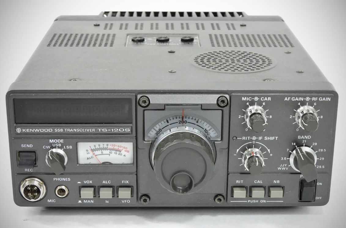
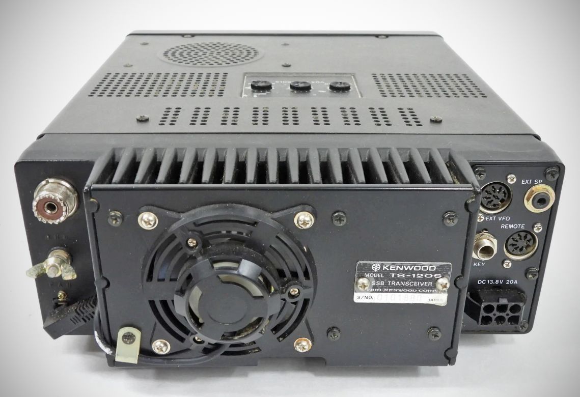
The Kenwood TS-120S and TS-120V are high-performance, solid-state, pre-WARC HF amateur radio transceivers designed for SSB and CW communication. Built with mobile, field, and fixed base-station operations in mind, they feature a highly compact and lightweight design.
The primary difference between the two models lies in their transmitter final output stages, with the TS-120S operating as the high-power variant and the TS-120V as the low-power (QRP) variant.
TS-120S (High-Power Version): Features a final stage with push-pull 2SC2290 power transistors.
80m through 15m bands: 200W PEP input for SSB; 160W DC input for CW.
10m band: Reduced to 160W PEP for SSB; 140W PEP for CW.
TS-120V (Low-Power/QRP Version): 25 watt power output designed to reduce overall current drain for portable operations.
Features
– All Solid-State & No-Tune Final: The broadband design of the final amplifier removes the traditional need for manual transmitter transmitter tuning or dipping/peaking controls.
– Built-in Digital Display: Features a dual vacuum fluorescent display tube system that reads out operating frequency down to an accurate 100 Hz interval across all operating modes and bands.
– IF Passband Tuning (IF Shift): Includes a built-in IF SHIFT system allowing the operator to manually shift the intermediate frequency passband to reject or eliminate adjacent channel interference.
– Single Reference Crystal Architecture: Departing from older transceiver architectures (like the TS-820 series), the TS-120 runs the Phase Locked Loop (PLL) lock frequency for every single band, the internal counter clock, and the calibration marker off of one single master reference frequency crystal. This completely eradicates frequency drift errors caused by delta differences between separate heterodyne crystals.
– Fixed-Channel Capability: Operators can install up to four optional auxiliary crystal-controlled fixed channels (one apiece for the 7, 14, 21, and 28 MHz selections). The 3.5 MHz and 28 MHz fixed crystal positions can be easily inverted via an internal jumper hookup on the AF-GEN circuit board.
– Single-Conversion Receiver System: Implements an 8.83 MHz intermediate frequency (IF) single-conversion system. The front end utilizes a shared transmit/receive bandpass filter (BPF) that removes the need for a separate preselector control. Dual-gate MOS FET balanced mixers (3SK74) drive the signal to ensure strong resistance against intermodulation and out-of-band spurious responses.
– Fully equipped with VOX, a balanced-gate noise blanker, a semi-break-in CW keying system complete with side-tone audio monitoring, and a 25 kHz crystal marker calibrator.
– Advanced Multi-Tier Protection Circuits: VSWR Protection: Toroid coils in the filter assembly continuously monitor forward and reflected power. If an improper impedance mismatch is detected at the antenna port, the circuit dynamically throttles back the forward drive voltage to protect the expensive final power transistors.
– Thermal Overload Protection: Features multi-stage thermal defense. An active thermistor circuit kicks on a cooling fan when the heat sink hits approximately 45°C. If the core transformer exceeds 120°C or the primary heat sink shoots past 90°C due to continuous transmission stresses, the unit forcefully trips the ALC line off, drops out of transmit mode, and forces the radio safely into receive mode until it cools down.
Specifications
Based on the official Kenwood service documentation, here are the technical specifications copied directly from the manual for the TS-120 series (TS-120S and TS-120V):
Specifications
– Frequency Range:
80 m band: 3.5 ~ 4.0 MHz
40 m band: 7.0 ~ 7.3 MHz
20 m band: 14.0 ~ 14.35 MHz
15 m band: 21.0 ~ 21.45 MHz
10 m band A: 28.0 ~ 28.5 MHz
10 m band B: 28.5 ~ 29.0 MHz
10 m band C: 29.0 ~ 29.5 MHz
10 m band D: 29.5 ~ 29.7 MHz
WWV: 15.0 MHz (receive only)
– Mode: SSB, CW
– Antenna Impedance: 50 ohms
– Receiver Sensitivity: 0.25 µV for S/N 10 dB or better
– Image Ratio: Image frequency better than 50 dB down from the output signal
– IF Rejection: IF frequency is 70 dB or more down from the output signal
–Frequency Stability: Within 100 Hz during any 30 minute period after warm up; Within ±1 kHz during the first hour after 1 minute of warm up.
– Selectivity: SSB, CW: 2.4 kHz (–6 dB), 4.2 kHz (–60 dB)
– AF Output: More than 1.5W (8 $\Omega$ load, 10% distortion)
– AF Load Impedance: 4 ~ 16 $\Omega$ for both speaker and headphone
– Power Input:
80 m ~ 15 m band: 200W PEP for SSB operation, 160W DC for CW operation
10 m band: 160W PEP for SSB operation, 140W PEP for CW operation
– Carrier Suppression: Carrier better than 40 dB down from the output signal
– Sideband Suppression: Unwanted sideband is better than 50 dB down from the output signal
– Mic. Impedance: 500 ohms ~ 50 k ohms
– Audio Frequency Response: 400 ~ 2600 Hz (–6 dB)
– Harmonic Radiation: Better than 40 dB down from output signal
Power Requirements: 12 ~ 16V DC (Nominal: 13.8V)
Power Consumption (at DC 13.8V):
Transmit: Less than 18A in transmit (less than 1:5 SWR ratio)
Receive: Less than 0.7A in receive
Optional System Accessories:
PS-30 regulated base station power supply.
VFO-120 remote external VFO.
AT-120 portable antenna tuner.
SP-120 external communications speaker.
YK-88C 500 Hz crystal filter.
Optional YK-88C CW Filter Specifications
Center frequency: 8830.7 kHz
Center frequency deviation: Less than ±150 Hz (6 dB)
Passband width: 500 Hz (–6 dB)
Attenuation band width: 1.5 kHz (–60 dB)
Ripple: Less than 2 dB
Minimum loss: 6 dB ±2 dB
Guaranteed attenuation: Less than ±2 kHz ~ ±1 MHz / More than 80 dB
Terminal impedance: 600 ohms ±5%, 15pF ±5%
References
Review. QST, Feb 1980, p. 38.