Note
QST, Oct 1973, inside front cover.
TS-520S
QST, Jul 1977, pp. 144–145.
QST, Aug 1977, p. 163. (full specs)
TS-520SE
QST, Aug 1979, back cover.
QST, Sep 1979, p. 6. (full specs)
QST, Jan 1980, p. 99.
QST, Apr 1981, p. 164.
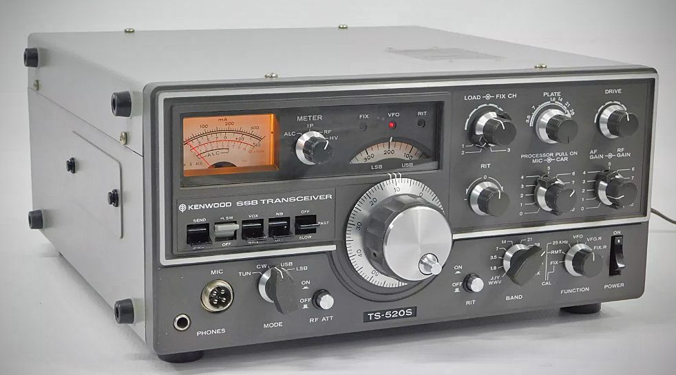
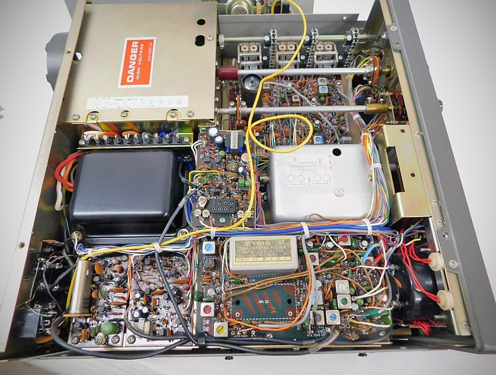
The Kenwood TS-520 is a sophisticated, modularly constructed amateur radio transceiver designed for operation from 80 and 10 meters. Featuring a solid-state design, the unit utilizes only three vacuum tubes in the final power stages to achieve high-power performance while remaining efficient enough for portable and mobile use. The transceiver is built around easily removable circuit boards, facilitating maintenance and reliability.
Features
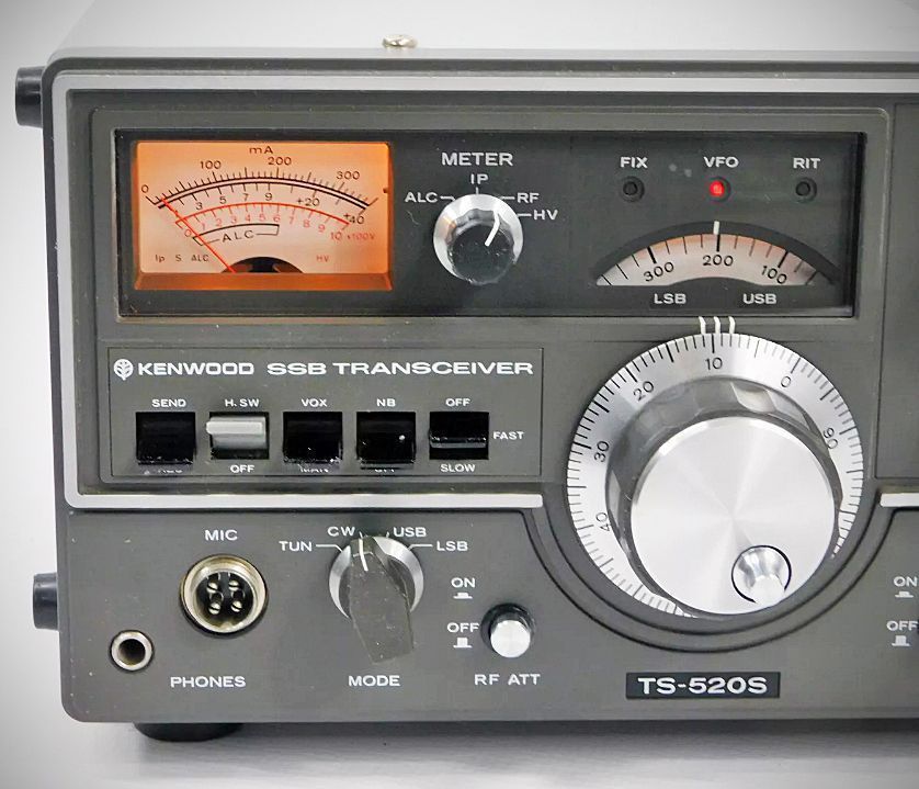
The TS-520 integrates several advanced features into its standard configuration, including a VOX (voice-operated transmission) circuit and a 25 kHz crystal calibrator for precise frequency alignment. For enhanced signal reception, it incorporates a Receiver Incremental Tuning (RIT) circuit, which allows the operator to adjust the receive frequency by more than ±2 kHz without affecting the transmit frequency. It also includes an effective noise blanker, a multi-stage RF attenuator, and automatic gain control (AGC).
Transmitter performance is augmented by a built-in speech processor for increased talk power during DX operations, as well as an automatic level control (ALC) system. For CW operators, the unit provides break-in capabilities with an integrated sidetone. Additionally, the transceiver is compatible with the optional DG-5 digital display, enabling frequency readings accurate to 100 Hz.
Beginning in Oct 1975, Henry Radio would add a digital display to a stock a TS-520. Purchased together, the cost was $729.00. To have a TS-520 retrofitted with the display cost $129.00.
TS-520S
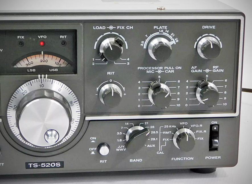
The TS-520S retains all of the features of the original TS-520: RIT control • 8-pole crystal filter • Built-in 25 KHz calibrator • Front panel carrier level control • Semi-break-in CW with sidetone • VOX/PTT/MOX • TUNE position for low power tune up • Built-in speaker • Built-in Cooling Fan
• Provisions for 4 fixed frequency channels • Heater switch.
The transition from the Kenwood TS-520 to the TS-520S represented a significant mid-generation update that addressed both band coverage and the burgeoning demand for digital frequency readouts. While the two transceivers share the same fundamental architecture and "hybrid" design—using solid-state circuitry for the low-level stages and vacuum tubes for the final power amplifier—several key technical and functional changes define the "S" model.
The most prominent functional difference is the inclusion of the 160-meter band. While the original TS-520 covered 80 through 10 meters, the TS-520S expanded this range to include 1.8 MHz to 2.0 MHz. This required modifications to the bandswitch assembly and the tank circuit to accommodate the lower frequency.
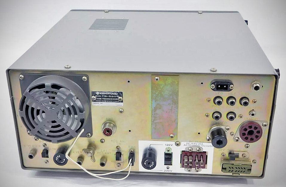
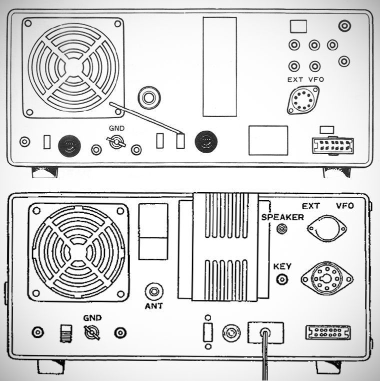
From a technical interface perspective, the TS-520S was designed to work seamlessly with the DG-5 digital display unit. To facilitate this, the "S" model features a dedicated digital display connector on the rear panel, which provides the necessary VFO, HET, and CAR signals to the external counter. The original TS-520 lacked this specific interface, making the addition of a digital readout a more complex task involving internal tapping of signals.
The internal processing of audio also saw an upgrade. In the TS-520S, the speech processor became a standard built-in feature, whereas earlier iterations of the original model often relied on external processing or simpler ALC-based clipping. This addition allowed for higher average talk power during SSB operations, which was a major selling point during that era of DXing.
Aesthetically and ergonomically, there were subtle refinements as well. The TS-520S introduced improved dial lighting and slight changes to the front panel nomenclature. Under the hood, the "S" model benefited from several years of production feedback, resulting in minor circuit refinements in the receiver's front end and noise blanker performance to improve signal-to-noise ratios in crowded band conditions.
TS-520SE
The Kenwood TS-520SE was introduced in 1979 as a streamlined version of the TS-520S. While it looks nearly identical to the "S" model and maintains the same core RF performance, it was marketed as a more economical, "Special Edition" base station.
The primary differences involve the removal of specific features that were standard on the TS-520S:
– AC-Only Power: Unlike the TS-520S, which could be operated on 13.8V DC using an optional internal DC-to-DC converter, the TS-520SE was designed strictly as an AC base station. The circuitry and connectors required for mobile DC operation were omitted.
– Removal of the Transverter Port: The TS-520S included a rear-panel transverter connector for use with external VHF/UHF equipment (like the TV-502 or TV-506). This port was removed on the SE model.
– No Fixed-Channel Capability: The TS-520S had a "FIX" position on the function switch and internal crystal sockets to allow for fixed-frequency operation (often used for net frequencies). The TS-520SE removed these sockets and the corresponding switch position.
– CW Filter as an Option: While the TS-520S often came from the factory or was easily upgraded with a narrow CW filter, the SE was strictly sold as an SSB unit with the CW filter being a separate, optional add-on.
– Auxiliary Band Position: The "AUX" position on the bandswitch (often used for WWV or transverters) was also removed or disabled in the SE version.
Despite these omissions, the TS-520SE retained the 160-meter band coverage and the ability to interface with the DG-5 digital display. It utilized the same "hybrid" architecture—solid-state receiver and exciter with 6146B vacuum tubes in the final power amplifier.
It was eventually replaced by the TS-530S series.
Specifications
TRANSMITTER
– Amateur Bands: 160-10 meters plus WWW (receive only)
– Modes: USB, LSB, CW
– RF Input Power SS8: 200 Watts PEP CW: 160 Watts DC
– Carrier Suppression: Better than –40 db
– Sidebard Suppression: Bette than –50 db
– Spurious Radiation: Better than –40 db
– Microphone Impedance: 50k Ohms
– AF Response: 400 to 2600 Hz
RECEIVER
– Frequency Stability: Within 100 Hz during any 30-minute period after initial warmup.
– Sensitivity: 0.25 uV for 10 dB (S+N)/N
– Selectivity: SSB: 2.4 kHz/–6 dB, 44 kHz/–60 dB
– Selectivity: CW: 0.5 kHz/–6 dB. 1.5 kHz/–60 dB (with optional CW 520 filter)
– Image Ratio: Better than 50 dB
– IF Rejection: Better than 50 dB
– AF Output Power: 1.0 watt (8 ohm load, with less than 10% distortion)
– AF Output Impedance: 4 to 16 ohms
Tubes (2) S2001A (6146B), (1) 12BY7A)
Transistors: 52
FETS: 19
Diodes: 101
Power Requirement
120/220 VAC, 50/60 Hz, 13.8 V DC (with optional DS-IA)
Transmit 280 watts; receive 26 Watts (with heater off)