Note
QST, May 1976, p. 6.
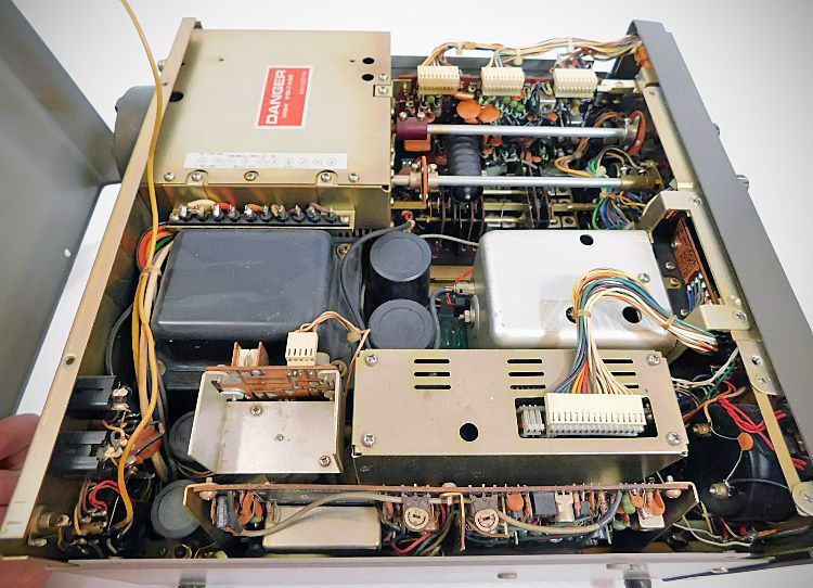
QST, Jun 1976, p. 90. (partial inside view)
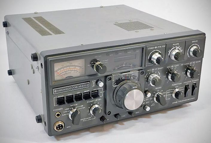
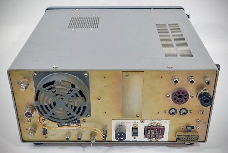
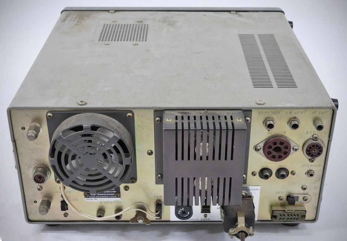
TS-820S
QST, Jul 1977, p. 132.
QST, Aug 1977, back cover. (good photo)
QST, Mar 1982, p. 145. (close out)
Introduced by Trio-Kenwood in 1976 as the successor to the wildly popular TS-520, the Kenwood TS-820 series (which includes the TS-820, TS-820S) is widely considered one of the finest "hybrid" transceivers ever built.
It represents the pinnacle of the hybrid era—combining rugged, high-voltage vacuum tubes in the transmitter final amplifier stage with cutting-edge, solid-state circuitry for the receiver, VFO, and intermediate stages.
To this day, hams celebrate the 820 series for its bulletproof construction, silky-smooth tuning, and warm, incredibly fatigue-free receive audio.
The TS-820 series relies on a classic, heavy-duty tube complement for the transmitter section:
– Driver: A single 12BY7A miniature pentode.
– Finals: Two 6146B beam power tetrodes running in parallel.
It delivers a solid 100+ watts output PEP on SSB and CW across the standard pre-WARC amateur bands (160, 80, 40, 20, 15, and 10 meters).
Unlike older rigs that relied on a complex web of crystals for mixing different bands, the TS-820 series was one of the first mainstream amateur transceivers to utilize a sophisticated Phase-Locked Loop (PLL) circuit. The single, highly stable analog VFO controls the injection frequency for all bands, resulting in incredible frequency stability and excellent linearity across the dial.
Standout Features for the Era
For the mid-to-late 1970s, the TS-820 series was a powerhouse of operator-centric features, many of which became industry standards:
– IF Shift: A breakthrough feature at the time. Rather than just narrowing a filter, IF Shift allows the operator to electronically slide the receiver's passband up or down to pass right over an interfering signal while keeping the desired signal's pitch natural.
– RF Speech Processor: Unlike simple audio clippers that add distortion, the TS-820 uses a sophisticated RF compression circuit operating at the intermediate frequency. It significantly increases "talk power" and punch on DX contacts without sacrificing audio quality.
– A built-in AC power supply, not common at the time.
– Fixed-Channel Capability: It features crystal-controlled fixed channels for net operations where jumping to an exact frequency instantly was required.
The TS-820 series cemented Kenwood's reputation for having the best sounding transmit and receive audio on the bands. Thanks to well-designed audio amplification stages and high-quality filtering, the receiver is exceptionally quiet, and the transmitted SSB signal is famously clean and "broadcast-quality" when paired with a good microphone like the Kenwood MC-50.
A complete, top-tier "820 Line" station in the late 70s was an impressive sight on a desk, typically consisting of:
– TS-820S Transceiver
– VFO-820 External VFO (allowing split-frequency DX operation)
– SP-820 External matching speaker (with selectable audio filtering)
– AT-200 Antenna tuner with a built-in SWR/Wattmeter
– SM-220 Station Monitor scope
Decades after its introduction, the TS-820 series remains a favorite among vintage amateur radio collectors. It sits in a sweet spot of engineering: it is complex enough to offer incredible performance, yet old enough to be completely serviceable. Because it uses discrete components, through-hole PC boards, and widely available tubes, a technician with a soldering iron, a service manual, and a steady hand can keep a TS-820 running indefinitely.
The primary difference between the base TS-820 and the TS-820S is the digital display.
– TS-820S: Came factory-equipped with the DG-1 digital display unit fully installed. The bright blue-green fluorescent digital readout on the front panel was a major selling point and a massive leap forward in technology for the mid-to-late 1970s.
– TS-820: Had a blank, smoked-plastic plate over that window and relied purely on the analog sub-dial for frequency readout. The digital display was sold separately as an optional accessory upgrade (the DG-1 kit).
While they are electrically identical in terms of the receiver, transmitter, and PLL circuit design, long-time owners and restorers point out a distinct physical difference in how they were manufactured over the production run:
The Original TS-820: Used a robust metal/plastic composite band switch coupler to connect the front-panel control shaft to the switches back in the final amplifier compartment.
The Later TS-820S: Switched over to an all-plastic nylon coupler. Over decades of heat and operation, this plastic version became notorious for cracking and slipping, making it a common point of restoration work today (often replaced with heavy-duty aftermarket metal couplers).
Beyond these two points, the transceivers share the exact same single-conversion receiver architecture, IF shift, built-in RF speech processor, and the classic hybrid tube final lineup (two 6146B/S2001A tubes driven by a 12BY7A).
Specifications
Frequency range: 1.8-29.7 MHz (160 - 10 meters)
Modes: USB. LSB. CW. FSK
Input power: 200W PEP on SSB 160W DC on CW, 100 W DC on FSK
Antenna impedance: 50-75 ohms. unbalanced
Carrier suppression: Better than –40 dB
Sideband suppression: Better than –50 dB
Spurious radiation Greater than –60 dB
(Harmonics more than –40 dB)
Receiver sensitivity Better than 0.25 uV
Receiver Selectivity SSB 2.4 kHz (–6 d8), 4.4 KH2 (–60 dB)
Receiver Selectivity: CW 0.5 kHz (–6 dB), 1.8 kHz (–60 B) (with optional CW filter installed)
Image ratio: 160-15 meters better than 60 dB, 10 meters better than 50 dB
IF rejection Better than 80 dB
Power requirements
120/220 VAC, 50/60 Hz.
13.8 VDC (with optional DS-1A DC-DC converter)
Power consumption: Transmit: 280 watts, receive 26 watts (heaters off)
References
Review. Popular Electronics, May 1977, p. 90.
Adding a QSK system. QST, Feb 1981, p. 32.
Frequency jumps. QST, Feb 1982, 50.