Note
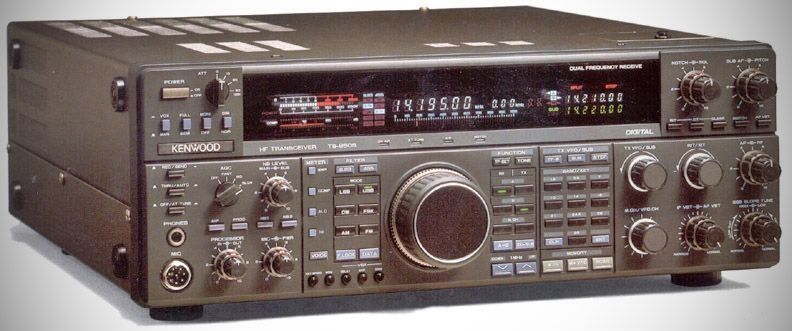
The Kenwood TS-950 series represents one of the final, massive peaks of the classic hybrid analog/early-digital contesting transceivers before high-performance IF-DSP completely shifted the landscape. Released in the late 1980s and early 1990s as Kenwood’s ultra-premium flagship, the 950 chassis saw three major variants, along with an internal hardware revision that is highly critical for anyone keeping them running today.
The TS-950SDX is sufficiently different from each others that it are listed in the Radio Alpha database in a separate entry.
Under the hood, the "TS-950S and SD radios share the exact same underlying analog chassis and receiver architecture.
– PA Section: They utilized a pair of 2SC2879 bipolar transistors running on 50V to deliver 150W output.
– Filtering & DSP: There was no DSP in the base ("S") version. It relied entirely on analog IF slope tuning, variable bandwidth tuning (VBT), and traditional crystal/mechanical filtering.
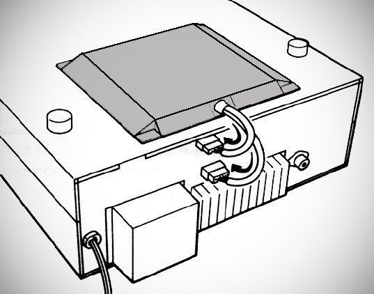
– Ergonomics: They featured a prominent top hatch on the cabinet hiding a sub-panel of adjustments (like VOX controls, beep levels, and drive settings) that you didn't need to tweak constantly.
The main difference is that the TS-950SD came from the factory with five expensive internal options pre-installed that you had to purchase and install separately if you bought the base TS-950S:
– The DSP-10 Digital Signal Processing Unit
This is the big one. The TS-950SD came with Kenwood's first-generation external-style DSP board pre-installed. On Transmit: It handles audio equalization, letting you adjust high- and low-cut frequencies for SSB and AM transmit audio, and shapes the CW waveform. On Receive: It acts as a variable-bandwidth audio filter (AF VBT).
– High-Stability TCXO (SO-2)
TS-950S: Relies on a standard reference crystal oscillator with a stability rating of 10 ppm within a temperature range of -10°C to +50°C. The TS-950SD includes the SO-2 Temperature-Compensated Crystal Oscillator (TCXO) as standard equipment, bringing the frequency stability down to a rock-solid ±0.5 ppm over that same temperature range.
– A Complete Suite of IF Crystal Filters
The "S" model, it came with standard bandwidth filters, leaving several filter slots empty. The "SD" model came fully loaded:
YK-88C-1: 500 Hz CW filter for the 8.83 MHz 2nd IF.
YG-455C-1: 500 Hz CW filter for the 455 kHz 3rd IF.
YG-455CN-1: 250 Hz Narrow CW filter for the 455 kHz 3rd IF.
YG-455S-1: 2.4 kHz SSB filter for the 455 kHz 3rd IF.
Features
– Memory: Includes 100 memory channels.
– Tuning Offsets: Features both Receiver Incremental Tuning (RIT) and Transmitter Incremental Tuning (XIT), each with a variable range of ±9.99kHz.
– Display: Features a digital display with a dimmer (DIM) switch to toggle between bright and dim illumination.
– Dual Frequency: Capable of Dual Frequency Receive.
– Main Receiver Circuitry: Utilizes quadruple conversion superheterodyne circuitry for Main SSB, CW, FSK, and AM reception.
– Sub Receiver Circuitry: Utilizes triple conversion superheterodyne circuitry for Sub SSB, CW, and FSK reception, and double conversion for Sub AM reception.
– Power Output: Provides output power ranging from 20W up to a maximum of 150W for SSB, CW, FSK, and FM modes. Output for AM mode ranges from 10W up to a maximum of 40W.
– CW Break-in: Features a FULL/SEMI break-in switch.
– Transmit Monitor: Includes a monitor (MONI) switch that allows you to listen to your own transmit signal.
Important Note: "Early" vs. "Late" S/SD Final Boards
For collectors and operators of the TS-950S and TS-950SD (non-X), there is an vital distinction between serial numbers regarding the Final Unit PCB layout:
– Early Production (Matte/Gloss Finish Variations):
The earliest runs used a final amplifier board that relied on a bias circuit setup prone to thermal runaway if component aging went unchecked. If a bias trimmer failed or drifted, it would instantly destroy the expensive 2SC2879 pair and burn traces on the board.
– Late Production (The "A" Board):
Kenwood recognized this vulnerability and completely redesigned the final unit board for later serial numbers. This updated board featured significantly enhanced thermal tracking, isolated bias circuitry, and overall better trace routing to protect the bipolar pairs from self-destruction.
When searching the used market for a 950S or SD, verifying whether the rig features the updated factory final board (or has been retrofitted with the late-style service board) is often the line between a lifetime bench keeper and an un-repairable parts rig.
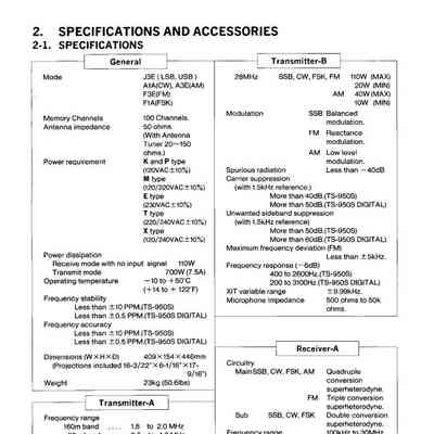
** For specifications, see the included excerpt from the user manual.