Note
Radio News, Oct 1957, p. 152.
Allied Radio catalog 1958 (copyright 1957), p. 228.
CQ, Mar 1958, p. 168.
QST, Nov 1958 p. 207.
Allied Radio catalog 1960 (copyright 1959), pp. 264–265, 397.
Allied Radio catalog 1961 (copyright 1960), pp. 278–279.
QST, Jan 1961, p. 176.
Allied Radio catalog 1962 (copyright 1961), pp. 282, 411.
QST, Nov 1962, p. 176. (R-100A)
Allied Radio catalog 1963 (copyright 1962), pp. 27, 290 (R-100A)
Allied Radio catalog 1964 (copyright 1963), pp. 63, 65, 226.
Allied Radio catalog 1965 (copyright 1964), pp. 68–69, 328.
Allied Radio catalog 1966 (copyright 1965), p. 76.
Allied Radio catalog 1967 (copyright 1966), p. 80.
Allied Radio catalog 1968 (copyright 1967), p. 458.
The S-meter for the R-100A is optional. See Allied Radio catalog 1964 (copyright 1963), p. 65.
Kit only.
Not actually referred to as the R-100 until Allied's 1960 catalog. Prior to 1960 it was called the model Y-726, which was actually part of the catalog number for the product.
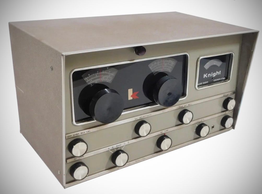
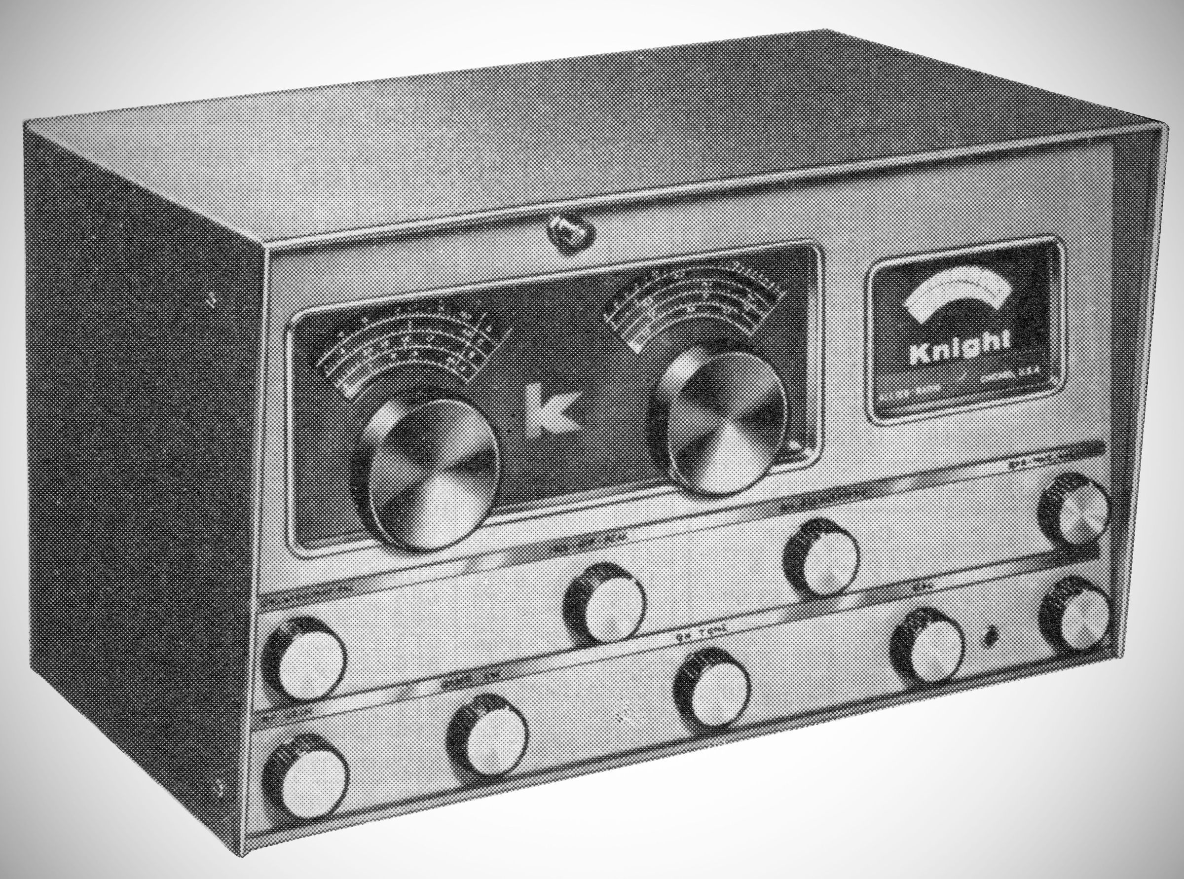
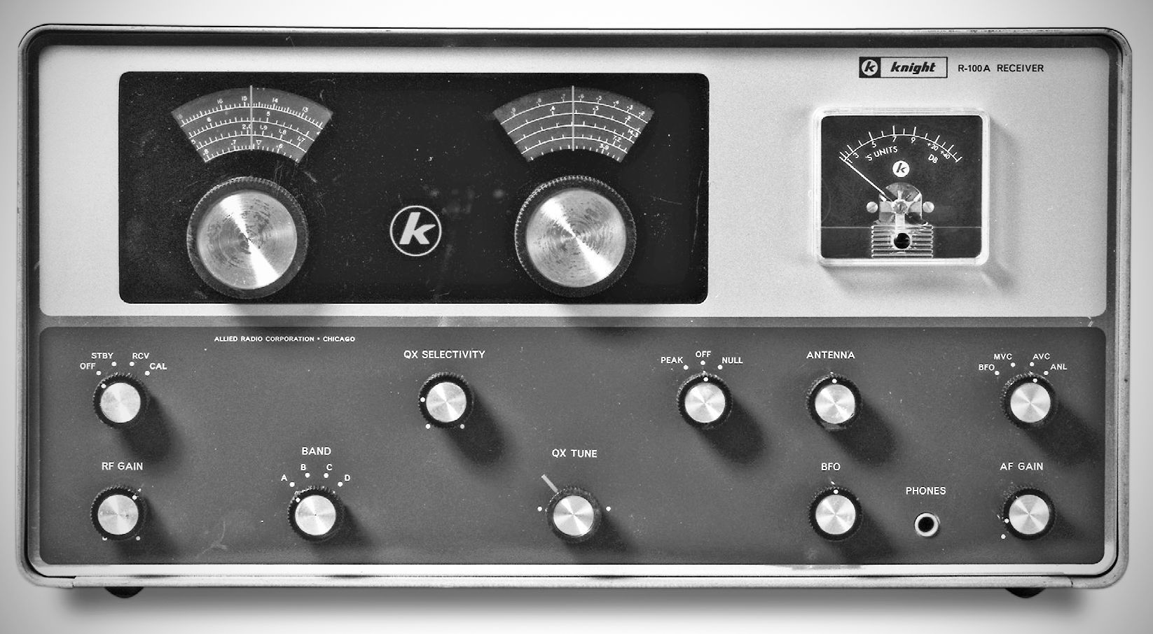
In 1962, Allied restyled the R-100 receiver to match their new Knight-Kit T-150 transmitter. The front-panel antenna trimmer was moved and labeled but, electrically, the nine-tube R-100A differed little from its predecessor.
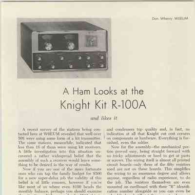
It uses printed circuit boards for ease of assembly, with 47 of its 50 resistors mounted directly on the boards.
Covers general coverage frequencies with a dedicated bandspread dial. The bandspread tuning ratio is roughly 6:1 over 165 degrees of the dial.
The R-100(A) is a single-conversion general-coverage superheterodyne circuit using nine vacuum tubes performing the function of 13 stages.
The receiver uses a 6BZ6 RF stage with panel-controlled RF trimming for tuning antenna loads. The 14, 21, and 28 MHz bands share a single RF coil. The mixer uses the pentode section of a 6HB6 tube, with its triode section serving as the conversion oscillator.
The unit features two IF stages utilizing 6AZ8 pentodes. The detector is a 6BC7 triple diode providing standard diode detection, delayed AVC action on weak signals, and an automatic series noise limiter.
The BFO uses the triode section of a 6AW8, injecting its output signal at a very low level into the second IF stage input for SSB/CW reception. It includes a built-in Q-Multiplier for peak and null selectivity control.
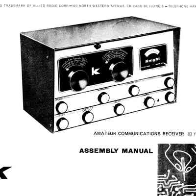
Here are the specifications for the Knight R-100 Amateur Communications Receiver from the manual:
Specifications
– Frequency Range
Band A: 0.54 – 1.65 MHz
Band B: 1.6 – 4.6 MHz
Band C: 4.4 – 12.4 MHz
Band D: 12 – 30 MHz
Calibrated Bandspread
80 m: 3.5 – 4 MHz
40 m: 6.9 – 7.3 MHz
20 m: 14.0 – 14.4 MHz
15 m: 20.5 – 21.5 MHz
10 m: 26.6 – 30 MHz
– Main Tuning: 0.7% Maximum deviation
– Bandspread: 0.15% Maximum deviation
– IF Frequency: 455 kc
– HFO Frequency:
Bands A, B, and C: 455 kc higher than incoming signal
Band D: Lower than incoming signal by 455 kc
– Variable Selectivity: 300 cps to 4.5 kc (6 db down); Up to 60 db null and 70 db peak
– Beat Frequency (BFO): Varies from zero beat to 5 kc
– Sensitivity:
Bands B, C, and D: 1.5 uV or better at 10:1 signal-to-noise ratio
Band A: 4.0 uV or better
– Image Rejection Ratio
Band A: 80 db (Low end) / 40 db (High end)
Band B: 68 db (Low end) / 30 db (High end)
Band C: 40 db (Low end) / 25 db (High end)
Band D: 40 db (Low end) / 20 db (High end)
– Audio & AVC
Maximum Audio Output: 0.5 Watt
Audio Output Impedance: 8 ohms
AVC: Delayed action over –2.0 V bias
– Antenna Input Impedances: Low-impedance coaxial or twin-line
Tube Complement (9 total)
– 6BZ6: RF Amplifier
– 6BH8: Mixer and High-Frequency Oscillator (HFO)
– 6AZ8: 1st IF Amplifier
– 6AZ8: 2nd IF Amplifier
– 6BC7: Detector / AVC / Automatic Noise Limiter (ANL)
– 6AW8A: BFO and Power Amplifier
– ECC83 / 12AX7: Q-Multiplier
– 6X4: Full-wave rectifier
– 0B2: Voltage regulator
Power Requirements: 117 VAC, 60 Hz, 45 watts
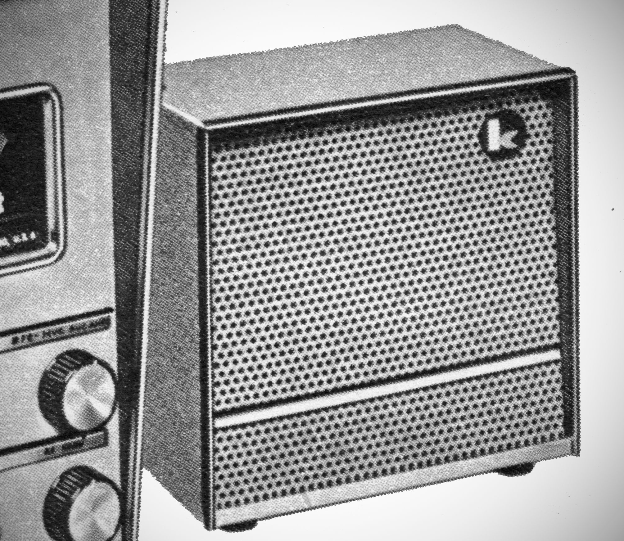
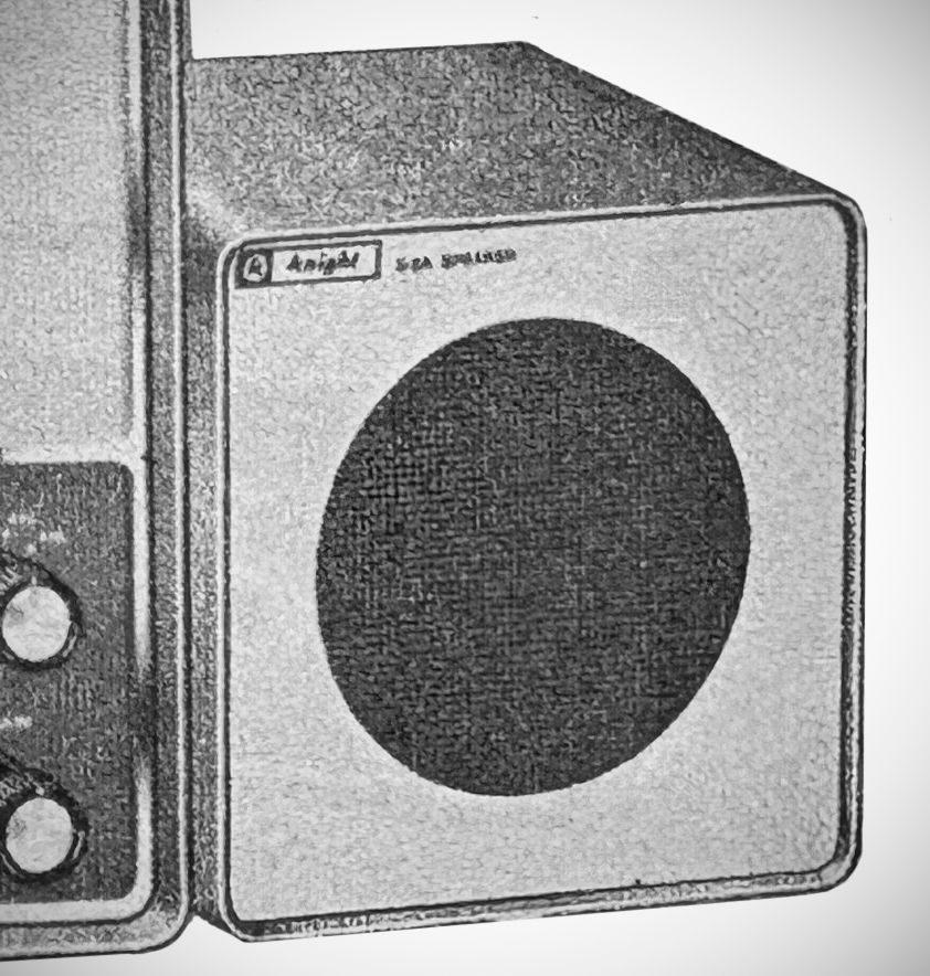
Accessories include a speaker (cat no. Y-728), an S-meter kit (cat no, Y-727), and a 100 kHz crystal calibrator (cat no. Y-256).
References
Review. Popular Electronics, Sep 1958, p. 71.