Note
QST, Nov 1962, p. 176.
Allied Radio catalog 1963 (copyright 1962), p. 26.
Allied Radio catalog 1964 (copyright 1963), pp. 63–64, 226.
QST, Jan 1964, p. 184. (T-150A) (released late in 1963)
CQ, Jan 1964, p. 112. (T-150A)
Allied Radio catalog 1965 (copyright 1964), pp. 66–67, 325.
> Does not appear in Allied's 1966 catalog.
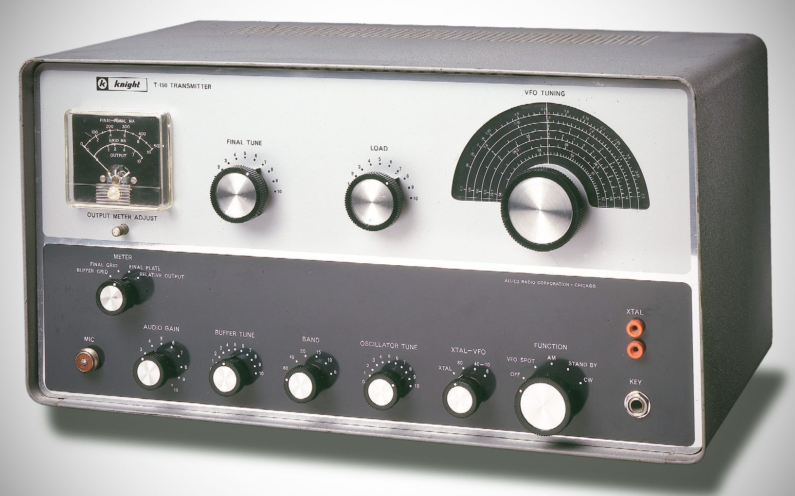
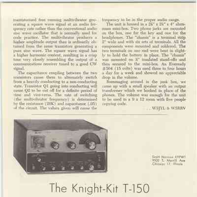
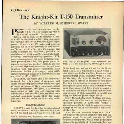
The Knight-Kit T-150 ran 150 watts input, AM and CW, on 80–10 meters, and 100 watts on 6 meters. It had a VFO and used controlled-carrier screen modulation of the 6146 finals on AM.
– Bands: Covers the 80, 40, 20, 15, 10, and 6-meter amateur bands.
– DC Final Input: 150 watts on 80–10 meters; 100 watts on 6 meters (CW or controlled-carrier phone).
– RF Power Output: 90 watts on 80–15 meters, 55 watts on 10 meters, and 40 watts on 6 meters.
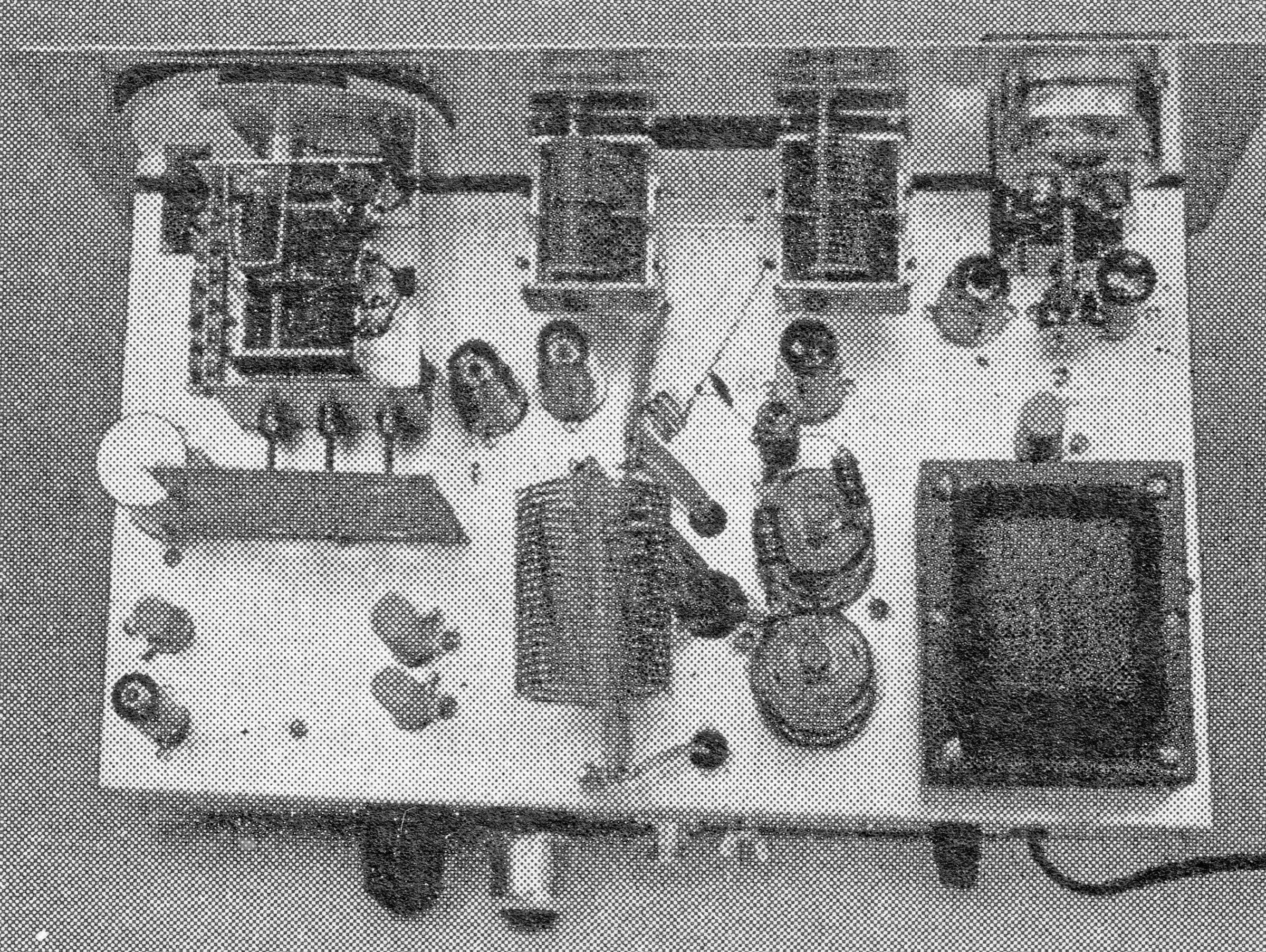
– VFO/Crystal: Includes a self-contained Clapp VFO utilizing a 12BY7 tube. It also supports crystal control using 3.5, 7.0, or 8.3 MHz crystals, which disables the VFO and uses the subsequent 6CL6 buffer as a modified Pierce oscillator.
– Output Network: Features a pi-network output matching loads from 40 to 600 ohms.
Uses solid-state silicon diodes in a voltage-doubler circuit to minimize internal heat and reduce chassis footprint.
External Modulator Provision: Includes an octal socket on the rear panel with connection points to hook up an external plate modulator for maximum power output.
Rear Accessory Outlets: Features an 11-pin socket providing switched 117 VAC for an external antenna relay, transmit/receive switching terminals, and DC voltages (700 VDC @ 50 mA, 300 VDC @ 50 mA, and 6.3 VAC @ 0.5 A) to power auxiliary station accessories.
Power Requiements: 115 VAC nominal; 350 watts max.
References
Review: QST, Jan 1963, p. 52.
Review. 73, Jan 1963, p. 48.
Brief description. Popular Electronics, Mar 1963, p. 39.
Brief description. Electronics World, Mar 1963, p. 98.
Review: CQ, Apr 1963, p. 41.