Note
QST, Nov 1961, p. 200.
Allied Radio catalog 1962 (copyright 1961), p. 410.
QST, May 1962, p. 176.
Allied Radio catalog 1963 (copyright 1962), p. 28.
Allied Radio catalog 1964 (copyright 1963), pp. 69, 226.
Allied Radio catalog 1965 (copyright 1964), pp. 72, 325.
Allied Radio catalog 1966 (copyright 1965), p. 75.
Allied Radio catalog 1967 (copyright 1966), p. 78.
Allied Radio catalog 1968 (copyright 1967), p. 456.
Paired with the R-55 receiver.
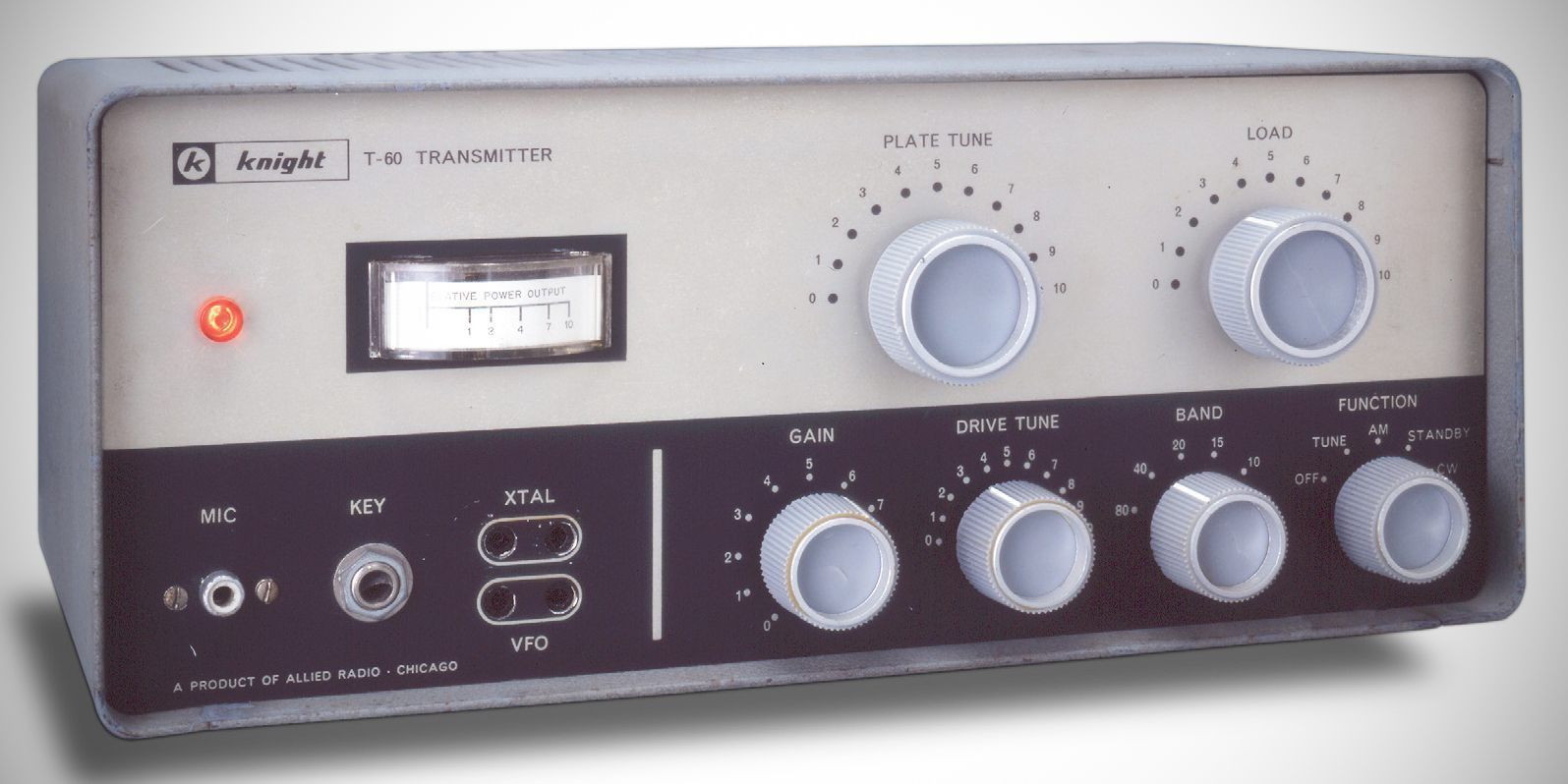
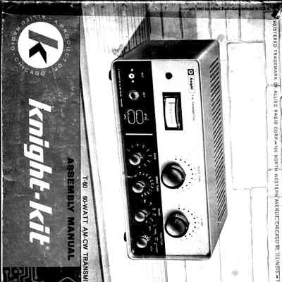
The Knight-Kit T-60 is a compact, versatile 60-watt AM/CW amateur radio transmitter kit produced by Allied Radio Corporation of Chicago, Illinois. Designed primarily as an entry-level first rig for Novice operators.
---
## Key Features & Frequency Coverage
– Operating Modes: Supports both CW and controlled-carrier AM (screen modulation).
– Power Output: Rated for a nominal power input of 60 watts to the final amplifier.
– Band Coverage: Features single-knob band switching across six amateur bands: 80, 40, 20, 15, 10, and 6 meters (covering 3.5 MHz through 54 MHz).
– Frequency Control: Operates via front-panel crystal inputs or an external Variable Frequency Oscillator (VFO).
– Antenna Matching: Equipped with an adjustable output Pi-network matching antenna impedances ranging from 40 to 600 ohms via a coaxial output connector.
Tube Lineup (4 total)
The transmitter operates using a four-tube complement along with semiconductor rectifiers and diodes:
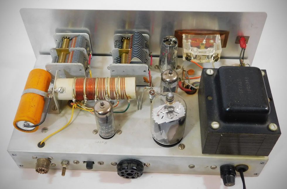
– 6HF8: crystal oscillator / buffer/ frequency multiplier.
– 12AX7: two-stage speech amplifier.
– 6DR7: modulator.
– 6DQ6B: RF power amplifier.
Semiconductors: Incorporates two silicon rectifiers for high-voltage DC rectification and a crystal diode in the relative RF power indication circuit.
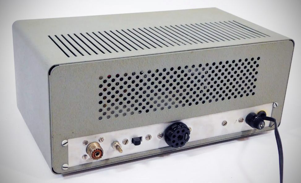
Accessory Socket: 8-pin connector for auxiliary control functions, such as antenna relays or external VFO power.
Power Requirements: 105–125 VAC, 60 Hz, 110 Watts.
References
Review: QST, May 1962, p. 60.
Adding break-in and PTT. 73, Aug 1962, p. 58.
Review: CQ, May 1963, p. 36.
Description. Popular Electronics, Sep 1962, p. 58.