Note
Allied Radio catalog 1967 (copyright 1966), p. 86.
Allied Radio catalog 1968 (copyright 1967), p. 453.
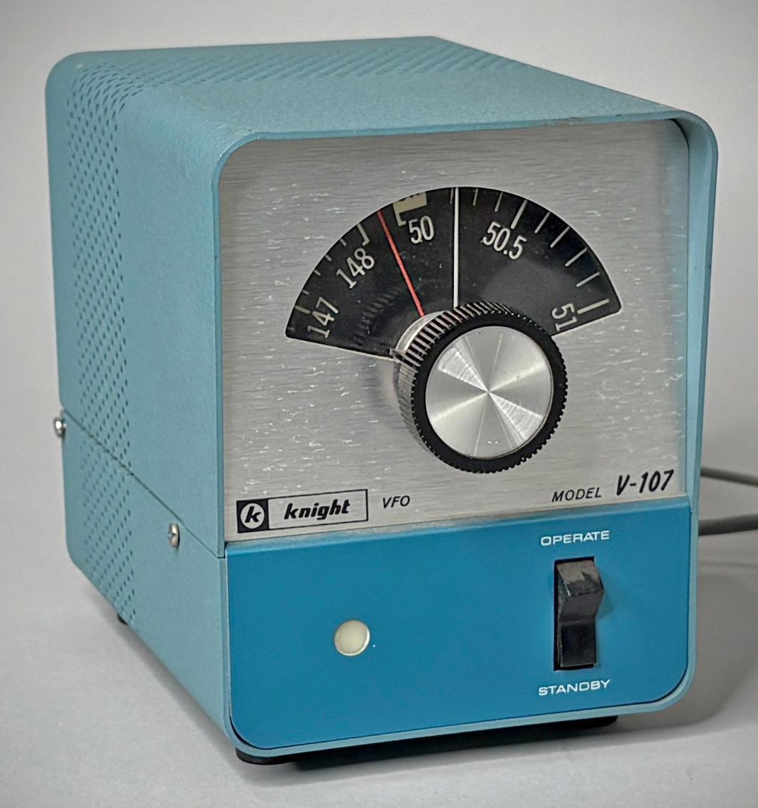
The Knight-Kit V-107 is an accessory variable frequency oscillator manufactured by Allied Radio Corporation and styled to match the TR-106 and TR-108 6 and 2 meter transceivers. Designed for desktop amateur radio setups, it can be physically mounted alongside a transceiver using an optional base accessory.
⚠️ The unit covers either the 6-meter band (specifically 50 to 52 MHz) or the full 2-meter band. It operates on one band at a time and requires realignment to switch between the two.
The V-107 uses a 12DK6 pentode functioning as an electron-coupled oscillator in a series-tuned Colpitts (Clapp) configuration. The screen grid acts as the triode oscillator plate, while the pentode plate—tuned to the oscillator frequency—delivers the output.
Frequency Ranges:
6 Meters: Operates from 8.333 to 8.666 MHz, which is multiplied by the host transmitter to cover 50 to 52 MHz.
2 Meters: Aligns to operate from 8.0 to 8.222 MHz.
RF Output: Rated at a minimum of 20 V RMS into a 47,000-ohm load shunted by 30 pF.
Features a 6:1 vernier-driven, backlit dial with two calibrated scales—one for 6 meters along one half of the perimeter, and one for 2 meters along the other half. The dial is positioned on the tuning capacitor shaft depending on the band for which the unit is aligned.
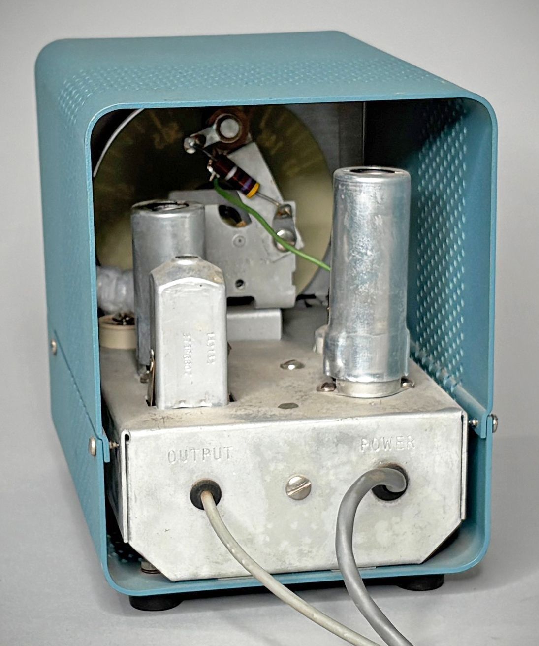
Employs a voltage regulator tube (enclosed in a tall shield on the chassis), temperature compensation, double-spaced tuning capacitor, and rugged mechanical construction to minimize thermal and mechanical drift. Operating voltages were specifically chosen to minimize harmonic output and reduce TVI.
Calibration is achieved by zero-beating against transmitter crystals using the spotting function on a receiver, or by directly tuning an 8.0 to 8.66 MHz receiver. Care must be taken during alignment to adjust the coil slug ($L_2$) to the proper beat point to ensure correct tracking across the dial.
Drift & Thermal Stability: From a cold start at ambient temperature, test measurements showed a 3 kHz drift in the first 30 minutes, 4 kHz over the second 30 minutes, and 1 kHz or less per hour thereafter. Unlike some VHF VFOs, it exhibits no frequency shift or creep at the start of individual transmissions.
Line voltage variations of ±10% produce a shift of only ±200 Hz, moving slowly with tube heater temperature changes.
RF Feedback Tuning: To avoid RF feedback (which can manifest as a slight output ripple), the output coil must be tuned while monitoring with a BFO receiver to ensure a clean, T9 signal near maximum output.
Power Requirements: Power is drawn externally (such as from the TR-106 ot TR-108 transceivers). External requirements are 12.6 V AC/DC at 150 mA and 200 V DC at 30 mA.
Review. QST, Oct 1966, p. 43.
Review. CQ, Nov 1966, p. 50.