Note
Lafayette catalog number 59, p. 93.
Radio, Jul 1935, p. 26.
Radio Craft, Jan 1936, p. 443.
Lafayette catalog number 65, p. 82.
Initially advertised for only 5 meters, but by Lafayette catalog 65 it included 2 1/2 meters.
Introduced in mid-1935 by the Wholesale Radio Service Co. of New York and marketed under the Lafayette Radio name, this 56-MHz (5-meter) receiver was offered as a simple, easy-to-assemble kit. It was designed in an effort to bring superheterodyne performance to the VHF spectrum, which at the time was dominated by simpler but less selective and high-radiation superregenerative receivers.
The original kit was priced at $16.75 less tubes, with an optional power supply kit available for $8.25, and a factory-wired option for an additional $3.25.
The design was a modification of a circuit by well-known technical writer and experimenter Frank C. Jones, W6AJF.
The initial model was a six-tube receiver utilizing standard 6.3-volt tubes, though constructors could also substitute equivalent 2.5-volt tubes:
Tube Lineup
– RF Stage: 6D6 tuned RF amplifier (primarily functioning as an antenna isolator to prevent local-oscillator radiation)
– First Detector/Oscillator: 6C6 autodyne stage
– IF Amplifiers: (2) 6D6 stages
– Second Detector/AVC: 41 pentode
– Audio Output: 42 power pentode (capable of driving a dynamic speaker)
Rather than using traditional intermediate frequency transformers, the receiver utilized a resistance-capacitance (RC) coupled IF system.
Passband: By pairing very small coupling capacitors (100 pF) with the inherent stray capacitance of the circuit, the design created a wide IF passband spanning roughly 15 to 100 kHz.
This specialized passband was intentionally chosen to pass the necessary intermediate frequencies while rejecting audio frequencies. This allowed the receiver to successfully capture the unstable, "wobbly" signals produced by the modulated-oscillator transmitters common to the 5-meter band in the 1935 era, offering better selectivity than a superregenerative set without completely suppressing the signal. It was also considerably cheaper for Lafayette to manufacture.
The autodyne oscillator circuit was unique: the grid circuit of the first detector was slightly detuned from the incoming signal frequency to produce a low-frequency beat note at the IF. Plate-to-grid feedback was achieved via a cathode RF choke.
The layout provided a few assembly variations depending on the operator's preference. While a 400-ohm RF gain control was part of the base design, it could be omitted in favor of an added 50k pot regeneration control to vary the DC voltage fed to the first detector from the 45-volt B.
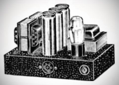
Coils: Designed with plug-in coils mounted on elevated stand-off pillars. This layout minimized the length of the grid leads and permitted the operator to swap in 10-meter or 2-meter coils if desired.
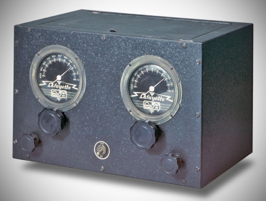
The front panel featured dual tuning dials. The initial 1935 models used plain dials with standard National-design knobs, which were later upgraded to branded "airplane" dials featuring the Lafayette logo.
By December 1935, Lafayette rapidly updated the receiver to address the weak gain of the original 6D6/6C6 front end.
In this upgraded version, the front-end tubes were replaced with newly released RCA 954 acorn UHF pentodes. The revised model relocated the antenna terminals to the side of the cabinet, added a dedicated B+ switch, moved the speaker jack to the rear apron, and featured the updated Lafayette-logo airplane dials. This acorn-tube variant was sold factory-wired for $26.50 (less tubes), with its matching power supply priced at $9.50.
Even after this premium variant was introduced, the original 6D6/6C6 electrical design remained popular among experimenters, appearing virtually intact (though with a modified layout) as a "7-Tube Resistance Coupled Super" in the 1937 Jones Radio Handbook.
References
Review: Radio Jul 1935, p. 20.
Technical description. Radio Craft, Jan 1936, p. 412.
Brief description. Radio News, Apr 1936, p. 598.