Note
Imported.
QST, Sep 1964, p. 163.
QST, Jan 1965, p. 131.
QST, Jan 1966, p. 133.
QST, Mar 1966, p. 143.
QST, Jan 1967, p. 127.
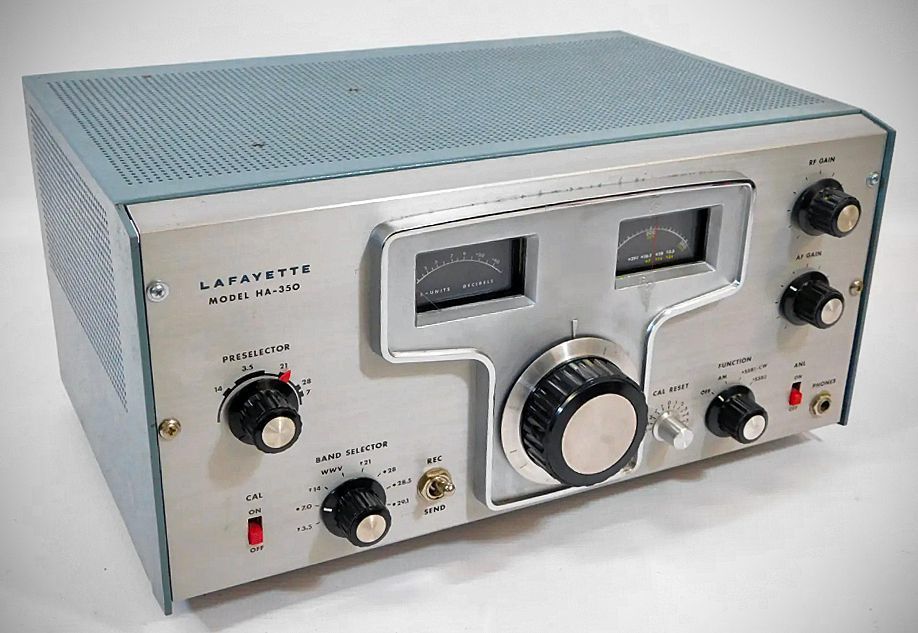
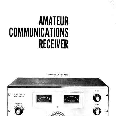
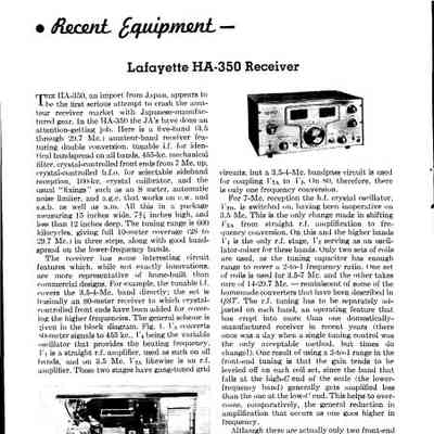
The Lafayette Model HA-350 is a dual-conversion superheterodyne communications receiver released in 1964, designed specifically for reception across the 80, 40, 20, 15, and 10-meter ham bands, along with dedicated coverage for WWV at 15 MHz.
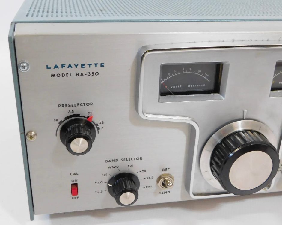
The HA-350 covers the main amateur service bands using a single main tuning dial calibrated directly in kHz, supplemented by a front-panel Preselector control to peak the RF and first mixer stages:
80 Meters: 3.5 to 4.0 MHz
40 Meters: 7.0 to 7.5 MHz
20 Meters: 14.0 to 14.5 MHz
15 Meters: 21.0 to 21.5 MHz
10 Meters: Divided across three 500 kHz segments (28.0–28.5 MHz, 28.5–29.1 MHz, and 29.1–29.7 MHz)
WWV coverage at 15 MHz
The 350 uses dual conversion on all bands except 80 meters, which operates as a single-conversion receiver. The first conversion stage uses a crystal-controlled oscillator driving a variable 3.5 to 4.1 MHz first IF stage. The second conversion stage utilizes a VFO running down to a fixed 455 kHz second IF.
High selectivity is achieved in the 455 kHz IF stage through a mechanical filter providing a 2 kHz bandwidth at 6 dB down and 6 kHz at 60 dB down. For CW and Single Sideband (SSB) reception, it uses a product detector coupled with a dual-crystal controlled BFO using 453.5 kHz and 456.5 kHz crystals) for selectable upper or lower sideband carrier reinsertion. AM signals are routed through a separate 1N60 diode detector circuit.
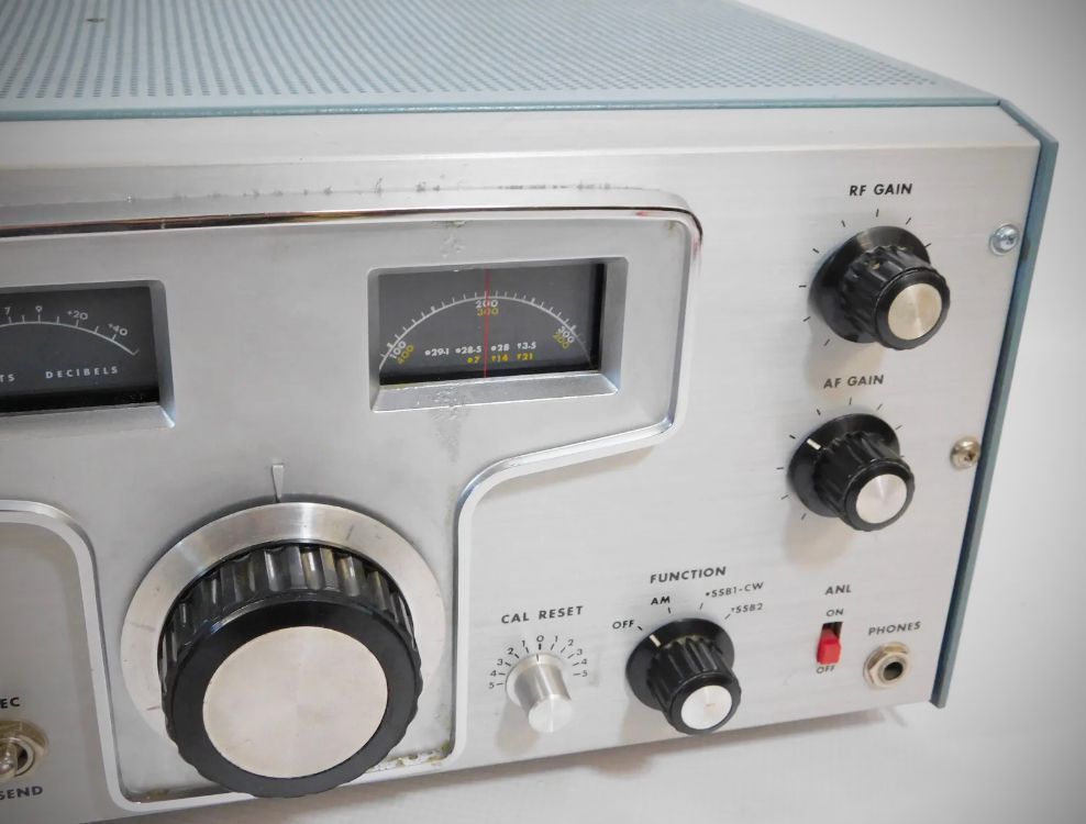
The front panel features an illuminated "S" meter, main vernier tuning dial, Preselector, Band Selector, Function switch (OFF, AM, SSB1-CW, SSB2), RF Gain, AF Gain, Calibration Reset, ANL toggle, and a 1/4-inch headphone jack.
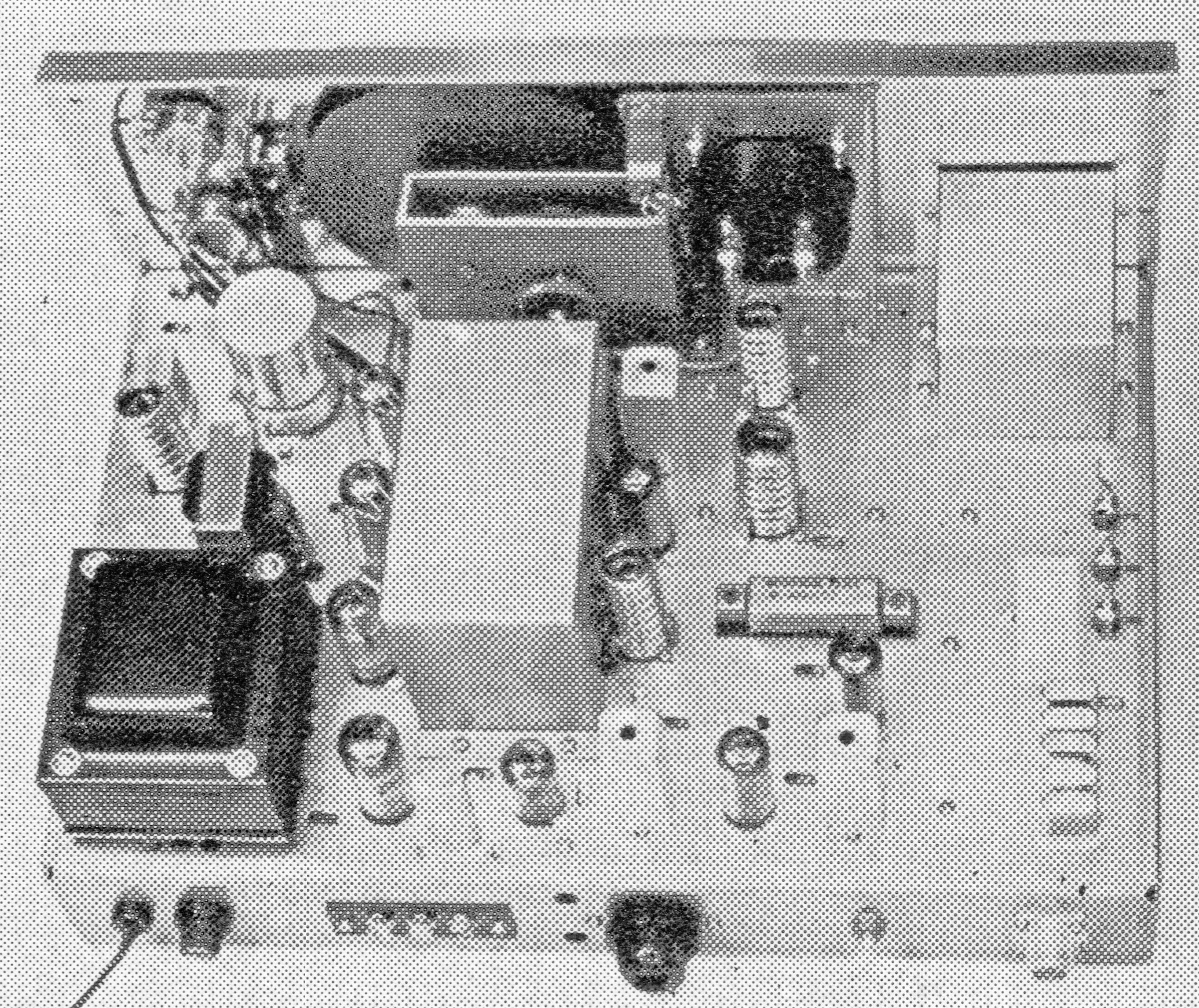
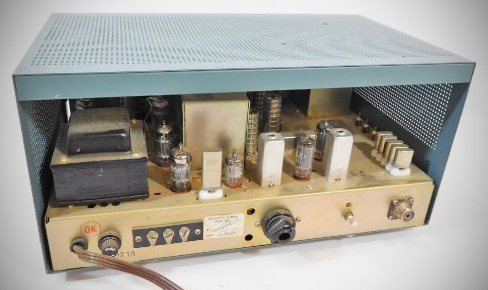
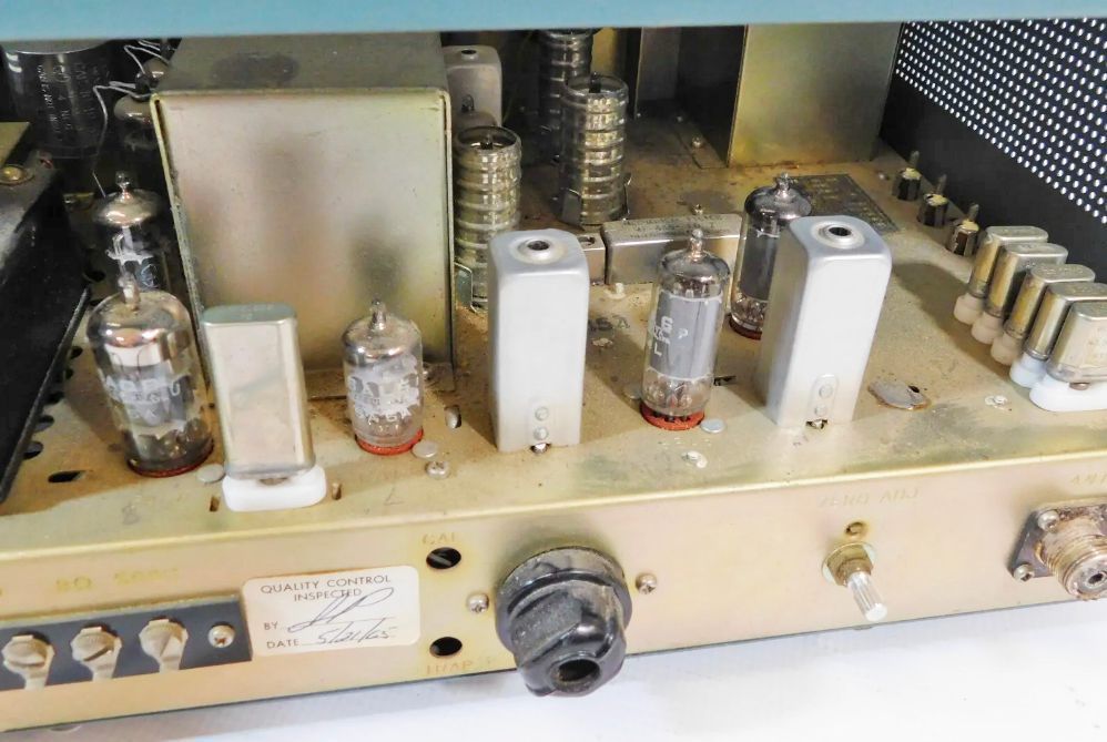
The rear apron provides an SO-239 connector for 50–75 ohm unbalanced coaxial antenna feeds, a 3-terminal speaker strip for 8-ohm and 500-ohm outputs, an 8-pin octal auxiliary socket for external transmitter muting or accessories, an "S" meter zero adjustment potentiometer, a socket for an optional 100 kHz calibration crystal, and a primary power fuse.
Specifications
– Frequency Coverage:
80m: 3.5–4.0 MHz
40m: 7.0–7.5 MHz
20m: 14.0–14.5 MHz
WWV: on 15 MHz
15m: 21.0–21.5 MHz
10m: 28.0–28.5 MHz
10m: 28.5–29.1 MHz
10m: 29.1–29.7 MHz
– Modes: AM, CW, and Selectable Single-Sideband
– Antenna Input: 50–75 ohms unbalanced (with coaxial connector)
– Sensitivity: Better than 1 µV for 10 dB S/N ratio
– Selectivity: Bandwidth 2 KHz at 6 dB down; 6 KHz at 60 dB down
– Image Rejection: Better than 40 dB
– IF Rejection: Better than 40 dB
– Intermediate Frequencies:
1st IF: Variable 3.5–4.1 MHz
2nd IF: 455 KHz
– Audio Output: 1 watt max
– Output Impedance: 500 and 8 ohms
Options: HA-94 matching speaker.
Tube Complement (12 total)
– 6BZ6: RF Amplifier
– 6BL8: Crystal-controlled 1st Conversion Oscillator & 1st Mixer
– 6BE6: 2nd Mixer
– 6BA6: VFO (2nd Conversion Oscillator)
– 6BA6: 455 kHz 1st IF Amplifier
– 6BA6: 455 kHz 2nd IF Amplifier
– 6AL5: AVC Rectifier & Automatic Noise Limiter (ANL)
– 6AQ8: Product Detector & 100 kHz Crystal Calibrator
– 6AV6: 1st Audio Amplifier
– 6AQ5: Audio Output Stage (1 watt maximum)
– 6BA6: Crystal-controlled BFO
– 0B2: Cold-cathode Gas Voltage Regulator for B+ stability on the oscillators
Power Requirements: 110–120 VAC, 50/60 Hz, 60 watts
References
Review. QST, Dec 1964, p. 50.
Add adjustable selectivity. CQ, Feb 1966, p. 59.