Note
Imported
73, Oct 1969, p. 111 (new product announcement)
QST, Dec 1969, p. 147.
QST, Jan 1970, p. 139.
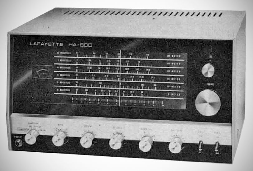
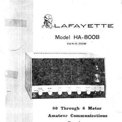
he Lafayette HA-800 and HA-800B are solid-state, double-conversion ham-band-only receivers covering 80 through 6 meters (plus WWV at 10 MHz).
Features
– Large Slide-Rule Dial: Features individual calibrated scales for each band and an integrated 0–100 logging scale.
– Fine Tune Control: Functions as a voice clarifier for SSB signals or a pitch control for CW reception by varying the first local oscillator frequency by ±1 kHz.
– Antenna Trimmer (ANT TRIM): Tunes the input circuit to match antenna systems ranging from 50 to 400 ohms for maximum sensitivity.
– RF Gain Control: Varies RF amplifier gain across all operating modes.
– Dual Mechanical Filters: Two 455 kHz mechanical filters provide steep skirt attenuation and high selectivity (pm 6 kHz bandwidth at 60 dB down).
– Product Detector & BFO: Dedicated product detector working in conjunction with a crystal-controlled beat frequency oscillator (BFO) for SSB and CW reception.
– Diode AM Detector: Separate detector circuit reserved for AM voice signals.
– Illuminated "S" Meter: Calibrated in S-units from 1 to 9 and in decibels above S9 (10 to 30 dB).
– Automatic Noise Limiter (ANL): Switchable circuit to suppress impulse noise during AM reception.
– 100 kHz Crystal Calibrator Circuit: Built-in calibration circuit activated via a front-panel switch (requires an optional 100 kHz crystal).
– Automatic Volume Control (AVC): Voltage-regulated AGC/AVC circuit for signal stabilization.
– Remote Socket & Jumper Plug: Octal rear socket allowing transmitter standby/receive relay control, audio routing, or remote speaker switching.
– Multiple Output Impedances: Screw terminals on the rear apron for 8,Omega and 500,Omega external speakers or lines.
– Tape Output Jack (`REC`): Phono/RCA output jack providing signal for direct tape recording.
Differences between the HA-800 and HA-800B
Calibration & Tuning Circuitry:
– HA-800: Uses a mechanical/capacitive main calibration arrangement connected via bus wire to the main tuning gang, which could make fine frequency alignment touchy and introduce local oscillator instability.
– HA-800B: Replaced the mechanical calibration scheme with an electronic varactor/potentiometer control to shift the oscillator frequency smoothly for zero-beating with the optional 100 kHz crystal calibrator. It also repositioned the fine-tuning/bandspread control for better electrical layout and improved SSB tuning stability.
– Local Oscillator Stability: Due to the revised component layout and VFO fine-tuning arrangement, the HA-800B experiences noticeably less mechanical microphonics and frequency drift compared to the earlier HA-800.
Specifications
– Frequency Coverage:
3.5 – 4.0 MHz
7.0 – 7.3 MHz
14.0 – 14.35 MHz
21.0 – 21.45 MHz
28.0 – 29.70 MHz
50.0 – 54.0 MHz
– Receiving Modes:AM, Standby, SSB, and CW
– Antenna Input Impedance:50 ohms
– Sensitivity:For 10 dB S/N ratio: 1 uV or better on all meter bands
– Selectivity:Bandwidth pm 6 kHz at 60 dB down
– Image Rejection:Better than 40 dB
– IF Rejection:Better than 40 dB
– Intermediate Frequencies:
First IF: 2.608 MHz
Second IF: 455 kHz
– BFO Frequency:455 kHz (Fixed)
– Fine Tune:Varies Local Oscillator pm 1 kHz
– Audio Output:1 watt (maximum), 500 mV Rec. output
– Output Impedance:8 and 500 ohms
– Auxiliary Circuits:Automatic Noise Limiter (ANL), Beat Frequency Oscillator (BFO), 100 kHz Crystal Calibrator Circuit (crystal optional), "S" Meter, Automatic Volume Control (AVC)
Transistor Complement (HA-800B) (20 total)
FET-1 (2SK19GR): 1st RF Amplifier
FET-2 (2SK19BL): 1st Mixer
FET-3 (2SK19GR): 1st Local Oscillator
FET-4 (2SK19BL): AGC Amplifier
TR-1 (2SC785R): 2nd RF Amplifier
TR-2 (2SC458B): 100kHz Calibrator
TR-3 (2SC784R): 2nd Mixer
TR-4 (2SC458B): 2nd Local Oscillator
TR-5 (2SC458C): IF Amplifier
TR-6 (2SC458C): IF Amplifier
TR-7 (2SC458B): AGC Amplifier
TR-8 (2SC458B): BFO
TR-9 (2SC458B): Product Detector
TR-10 (2SC712): Audio Amplifier
TR-11 (2SC712): Audio Amplifier
TR-12 (2SC1013): Audio Power Output
TR-13 (2SC1013): Audio Power Output
TR-14 (2SC712): DC Voltage Regulator
TR-15 (2SC712): DC Voltage Regulator
TR-16 (2SC458B): AGC Amplifier
Diode Complement:
D-1 (RD-7A): DC Voltage Regulator
D-2 (1S1503): Calibrator
D-4 (1N60): AGC
D-5 (1N60): AM Detector
D-6 (1N60): ANL
D-7 (1N60): ANL
D-8 (1S1210): Temperature Compensation
D-9 (1S1210): Temperature Compensation
D-10 (V06B): AC Rectifier
D-11 (V06B): AC Rectifier
D-12 (RD-7A): DC Voltage Regulator
Power Requirements: 105–120 VAC, 50/60 Hz
References
Brief description. Popular Electronics, Jan 1970, p. 24.