Note
QST, Dec 1961, p. 153.
QST, Jun 1962, p. 159. (HE-45A)
QST, Jan 1963, p. 159. (HE-45B)
For detailed information refer to Electric Radio magazine, Sept/Oct 2024, vol. 405.
Also, Electric Radio, vol. 318. (2015)
US made.
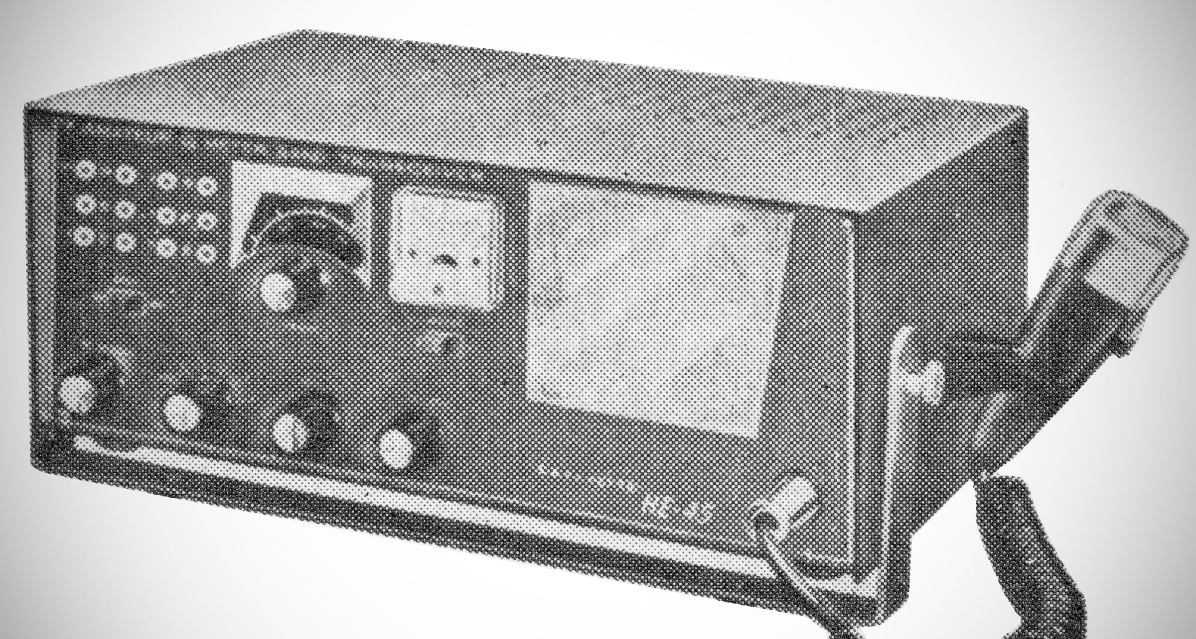
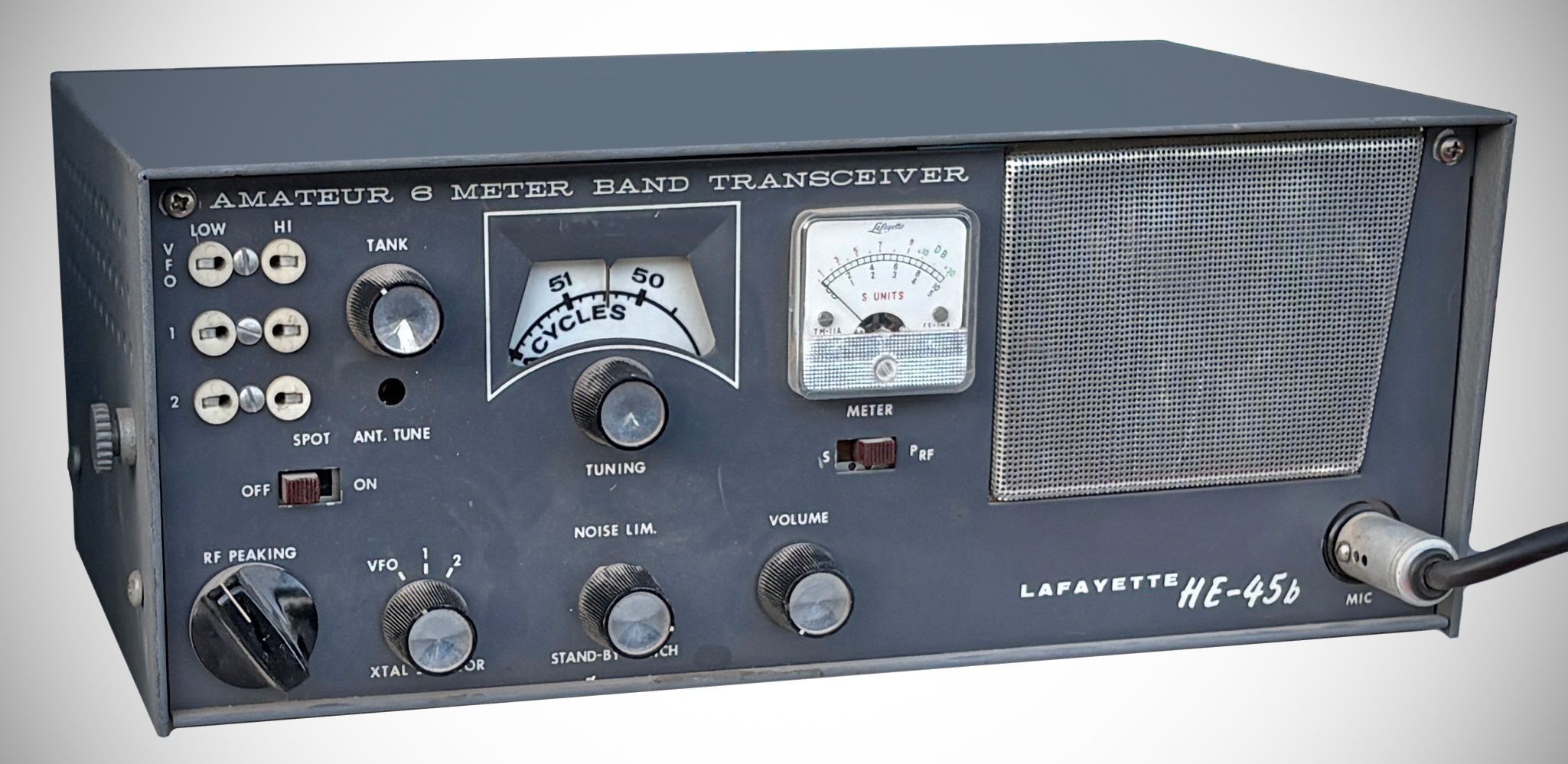
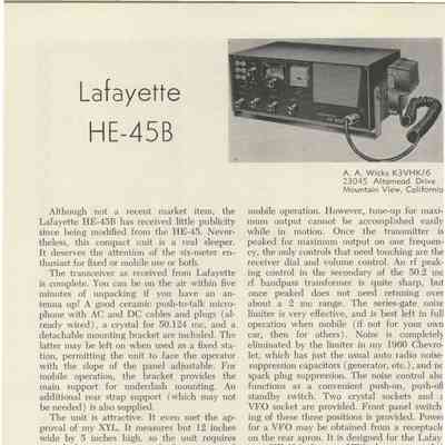
The Lafayette Model HE-45 is a 6-meter phone band transceiver (covering 50.1 to 54 MHz). It provides plate-modulated AM transmission and superheterodyne reception in a single compact desktop or mobile package.
Features
RF Peaking Control: A dedicated variable control that works alongside the main illuminated planetary vernier tuning dial to optimize receiver front-end sensitivity.
Spotting Switch: Allows the operator to calibrate and tune the receiver section directly to the active internal transmitter crystal frequency.
TV Interference Trap: Contains an internal series-resonant TVI trap connected in shunt across the antenna output connector to suppress harmonic interference on lower television channels.
Power Input: 12 Watts input to the final RF amplifier stage.
Final Output Tube: Utilizes a 2E26 beam power tube in a straight-through Class C configuration.
Features a 6-position selector switch on the front panel. It accommodates up to 5 crystal sockets for fundamental-type crystals (multiplied by 6 to reach the operating frequency) plus a 6th position dedicated to an external VFO.
Integrated variable "Pi" network is designed to match antenna loads ranging from 30 to 100 ohms.
The receiver is a superheterodyne design with an intermediate frequency of 1650 kHz.
Sensitivity is rated at 1 uV, with selectivity specified as 3 kHz down at 6 dB. Image rejection is rated at 45 dB.
Audio Output: 3 Watts into an internal 4-inch Alnico V speaker.
Incorporates an adjustable tuned RF bandpass stage preceding the detector to enhance sensitivity and selectivity while suppressing unwanted radiation.
Changes in the "A" and "B" version amounted to minor cicruit tweaks and a few changes in the tube lineup.
Power Requirements: Designed for dual power supply operation. It runs on either 117 VAC (60 Hz) drawing 60 Watts on receive and 85 Watts on transmit, or 12.6 VDC drawing 4.5 Amps on receive and 6 Amps on transmit.
Tube Lineup (8 total) ⚠️ Note: Tubes shown in (parenthesis) are used in the "B" version.
– 6BA6 (12BA6): R.F. amplifier.
– 6EA8: Mixer and oscillator.
– 12BA6 (12AU6): First IF amplifier.
– 6EA8: Second IF amplifier, microphone preamplifier
– 6CN7: Noise limiter, AF audio frequency amplifier.
– 6AQ5 (7868): Audio output, modulator.
– 6EA8: Crystal oscillator, tripler, and doubler.
– 2E26: Final amplifier.
References
Brief description. Electronics World, Feb 1962, p. 115.
Modifications. 73, Dec 1962, p. 10.
Modifications. 73, Nov 1965, p. 104.