Note
QST, Sep 1959, p. 175.
QST, Jan 1963, p. 167.
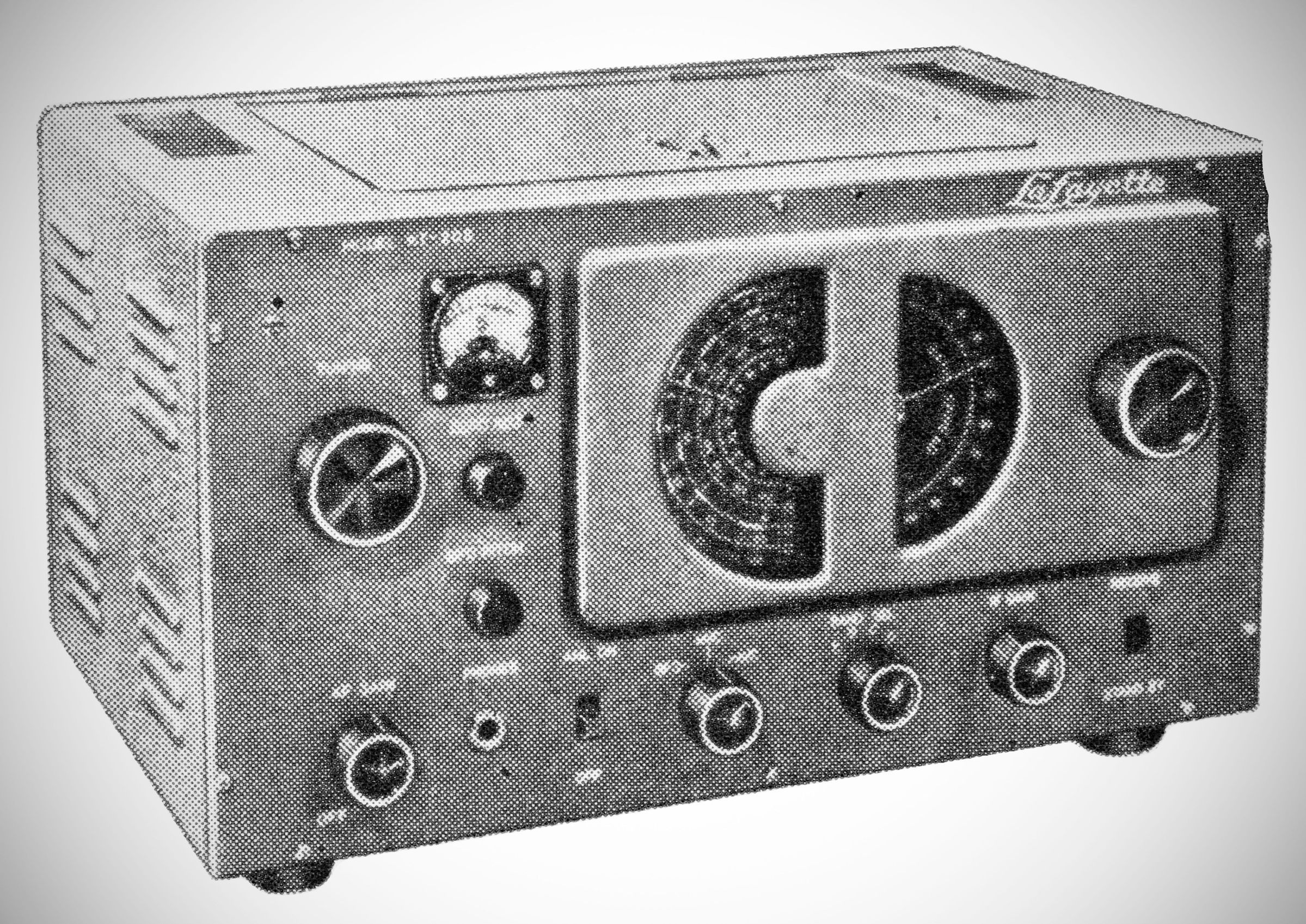
The KT-200 features a superheterodyne circuit utilizing a 9-tube line-up. A key design choice of this receiver is the separation of the local oscillator and the mixer into two distinct stages for improved operating stability.
The KT-200 is the kit version of the factory assembled HE-10.
Features a main tuning dial with four calibrated scales (one for each band) alongside a bandspread tuning control. Both dials include 0-100 logging scales.
Specifications
– Frequency Coverage: Tunes continuously from 550 kHz to 30 MHz across four bands.
– IF: 455 kHz
– Sensitivity: 1.25 uV for 10 dB Signal-to-Noise (S/N) ratio
– Selectivity: –60 dB at 1 MHz ±10 kHz
– Audio Output: 1.5 watts (capable of driving 4 or 8 ohm permanent magnet speakers)
Tube Complement
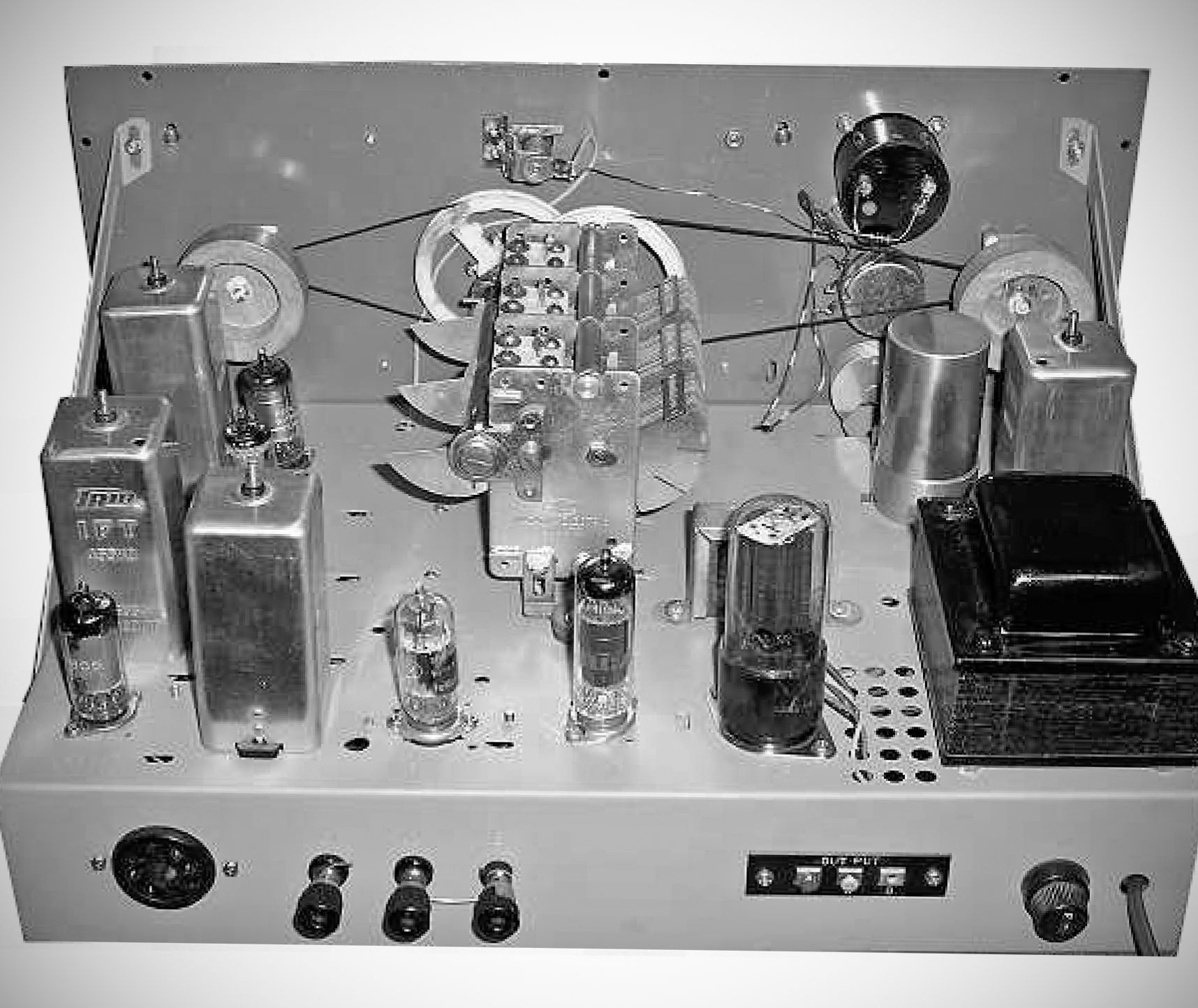
– 6BD6 High Gain RF Amplifier
– 6BE6 Mixer
– 6BE6 Local Oscillator
– 6BD6 1st IF Amplifier
– 6BD6 2nd IF Amplifier
– 6AV6 Dual Diode Triode (2nd Detector, AVC Rectifier, & 1st Audio Amp)
– 6AR5 Final Audio Output Amplifier
– 6AV6 Beat Frequency Oscillator (BFO) & Automatic Noise Limiter (ANL)
– 5Y3 Full-Wave Rectifier
Rear Panel Connections
Antenna Terminals: Labeled `A1`, `A2`, and `E`. They support an Inverted L single-wire antenna (with a jumper between `A2` and `E`) or a balanced doublet antenna utilizing a 300 ohm twin-lead transmission line.
Speaker Output: A three-terminal strip marked `OUTPUT`
Auxiliary Socket: A rear 5-pin socket allows an external transmitter switch to mute the receiver during periods of transmission.
Power Requirements: 100 - 125 VAC only, 50-60 Hz, 60 watts at 117 VAC
References
Brief description. Electronics World, Dec 1959, p. 130.
Brief description. Popular Electronics, Dec 1959, p. 24.