Note
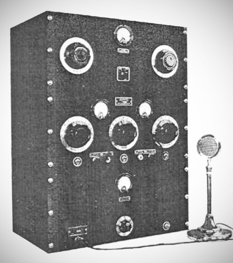
The Lafayette PB-46 is a vintage, 1930s-era amateur radio transmitter designed by Frank Lester (W2AMJ) and introduced in the 1936 catalog of the Wholesale Radio Service Company (which later became Lafayette Radio and Television). Marketed as a "Professional Rig for the 'Ham'," it was designed during the Great Depression as a high-quality yet accessible option for amateurs.
To accommodate cash-strapped amateurs, the PB-46 was offered as a pre-assembled and factory-tested system that could be purchased as a complete station with a steel cabinet for $116.50, or built up unit-by-unit as a "foundation kit". It was constructed across three independent decks designed for a standard 19-inch rack mount:
– Top Deck: The Antenna Coupler.
– Middle Deck: The RF (Radio Frequency) section.
– Bottom Deck: The heavy Modulator section.
The front panels are finished in a utilitarian black "crystalline lacquer" (commonly known as black crackle) with well-labeled metal tags for the controls and metering jacks. In contrast to its basic exterior, the chassis feature a premium, dressy cadmium plating with clean under-chassis wiring.
Specifications & Internal Components
1. RF Deck
– Oscillator: Utilizes a "Les-Tet" harmonic oscillator design employing a type 53 tube.
– Output Stage: Uses a pair of type 46 tubes running in Class C.
– Band Coverage: Supports multiple band operations using plug-in coils and crystals. It natively covers the 160, 80, and 40-meter bands with an average power output of 45 watts. It can also be pushed to operate on the 20-meter band at a reduced output of 37 watts.
– Metering: Features two front-panel meters (a lower current meter for early stages and a higher current meter for the output stage). Rather than modern switching, users change stages by inserting meter plugs into front-panel jacks—which carry B+ high voltage, requiring careful handling.
– Power Supply: Features its own onboard, independent power supply.
2. Modulator Deck
– Tube Lineup: Employs a 2A6 tube feeding into a type 46 driver, which pushes a pair of type 46 tubes running in Class B.
– Audio Output: Delivers 30 watts of audio power, perfectly matched to provide 100% modulation for the RF deck.
– Frequency Response: A highly respectable 60 to 17,000 Hz.
– Interface: Features a crystal microphone input jack, a gain control potentiometer, an on/off switch, a single meter, and a rear-panel AC power outlet to link the RF deck. It also contains its own onboard power supply.
3. Antenna Coupler Deck
– A simple but clever network consisting of two small air-variable capacitors and an antenna feed switch.
– Configurations: The switch allows the operator to configure the network into a parallel feed (where each capacitor tunes a feed line) or a series feed (which switches one of the variable capacitors out of the circuit).
– Metering: Uses a thermocouple inserted into one of the feed lines to drive a front-panel antenna meter, providing a relative RF power indication.
The transmitter was noted for being exceptionally user-friendly for its time. Getting on the air required only three basic connections: AC power, an antenna, and a key or microphone. Once tuned, it was advertised as delivering a sharp, crystal-controlled CW signal or a high-fidelity phone signal.