Note
QST, Dec 1958, p 186.
QST, Feb 1959, p. 120. (appears like a chassis-only kind of set up, different than the more finished product seen in Jul 1959)
QST, Jul 1959, p. 122.
QST, Mar 1960, p. 128.
QST, Dec 1960, p. 158. (2 meter version)
73, Feb 1962, p. 42.
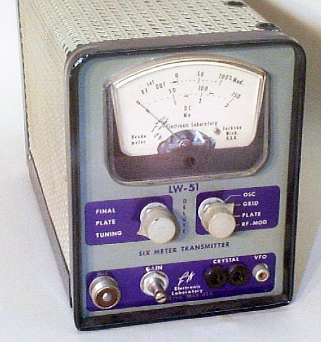
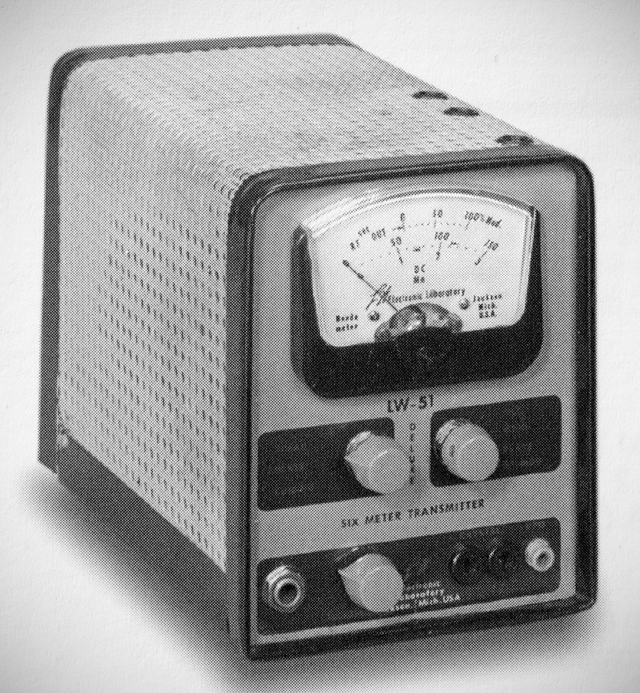
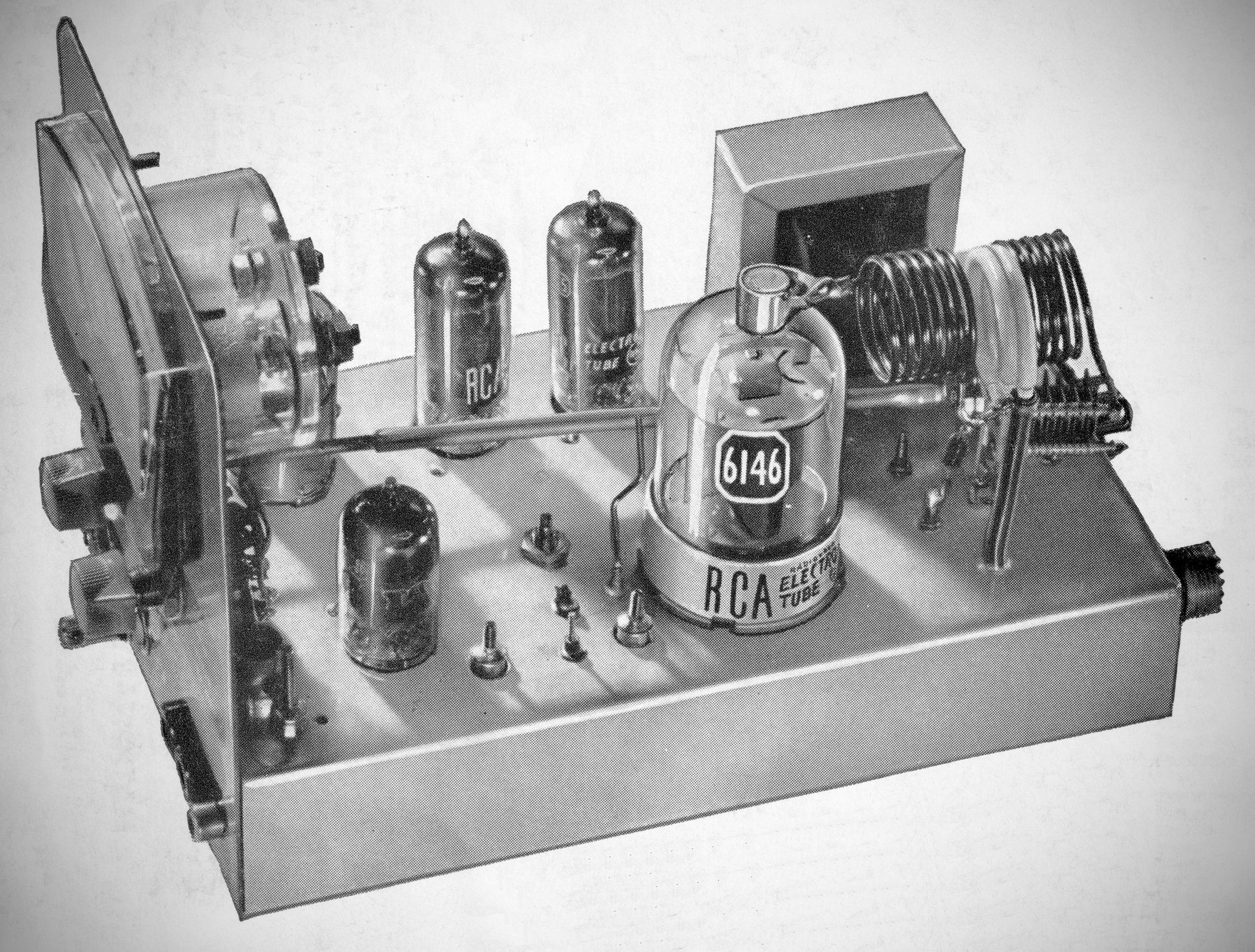
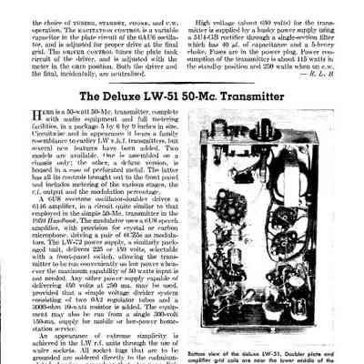
Electronic Laboratory of Jackson, Michigan made a line of 6 and 2 meter gear in the 1950s and early '60s .The LW-51 transmitter ran 50 watts input on 6 meters with a 6146.1t was plate-modulated. The factory-assembled LW-51 came with tubes and a crystal; the kit version did not. The LW-51 Deluxe included a cabinet and meter.
– Power Input: 50 watts
– Crystals: Uses standard FT-243 8 MHz crystals, with the final amplifier running straight-through at 144 MHz.
Uses the triode section of a 6U8A in a 24 MHz grid-oscillated circuit, while the pentode section triples the signal to 72 MHz. This drives a 7558 pentode that doubles the signal to 144 MHz.
Inductively coupled to a 6146 final tube to minimize harmonic coupling. The final stage incorporates a neutralization circuit and a link-coupled (adjustable) tank circuit connected to a coaxial output jack, paired with a variable capacitor to tune out line reactance.
A front-panel rotary switch allows the meter to monitor oscillator status, final grid current, final plate current, RF output, or modulation percentage.
Power Requirements: Designed with filaments configurable for either 6-volt or 12-volt operation to support fixed-station or mobile installations.
References
Review, QST, Dec 1959, p. 47.
Review, 73, Feb 1962, p. 42.