Note
Radio, Sep 1934, p. 28.
QST, Oct 1934, p. 111.
QST, May 1935, pp. 21-28.
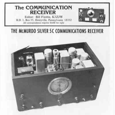
Marketed by McMurdo Silver during the early 1930s as part of a evolution of shortwave receivers (following the 5A and 5B models).
It was primarily promoted and sold by the Wilcox Sales Company of Chicago, as well as Delaware Radio Sales. Due to minimal, short-lived promotion and a lack of an effective dealer network during the Great Depression, very few were made, making it rare today.
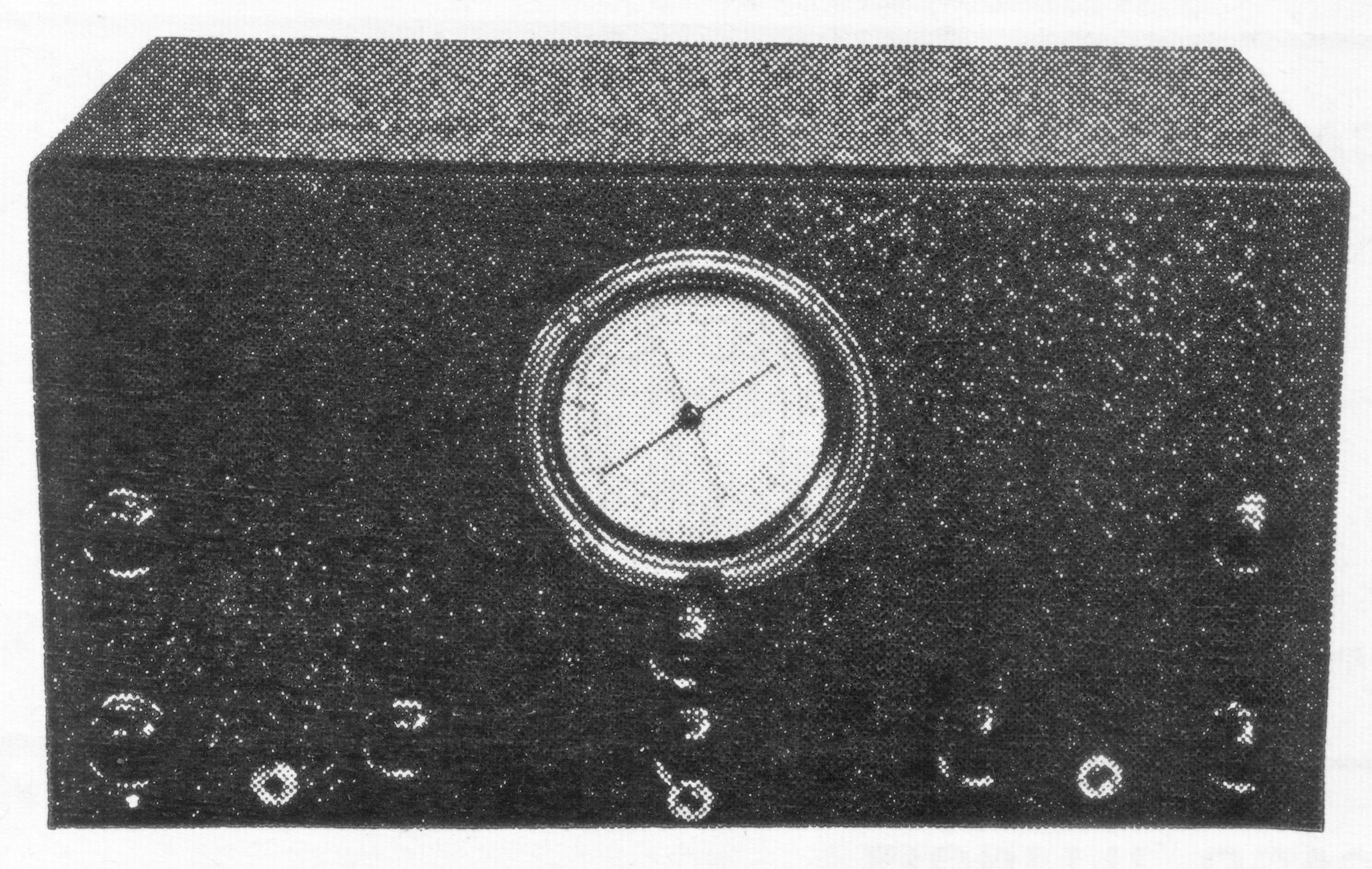
The front panel is highly utilitarian and completely lacks control nameplates or markings, featuring only a collection of unmarked knobs.
The actual receiver identification is printed directly on its 4-inch, round, airplane-type main dial. It features a two-speed tuning mechanism with two pointers.
It covers three tuning ranges spanning 1.5 to 23 mc (which are color-coded on the dial and the bandswitch). Notably, it has no broadcast band.
The 5C was built mostly using standard components of the era from high-quality broadcast receivers, though it featured a mix of premium choices and obvious cost-cutting measures:
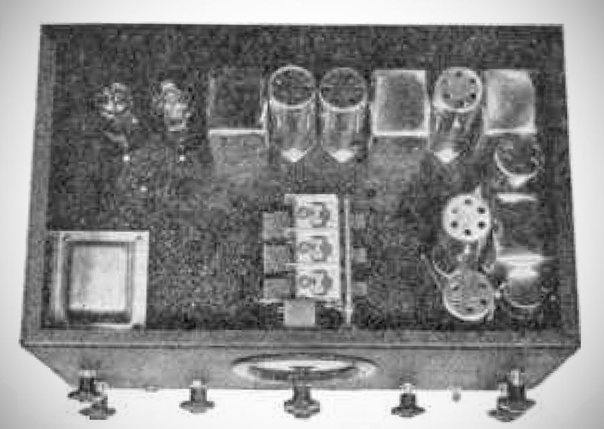
The IF transformers utilized air-tuned trimmer capacitors, which were considered a mark of high quality at the time. Additionally, the RF and oscillator coils—along with their associated bandswitch—were well-engineered and enclosed in a three-section compartment at the bottom of the chassis.
It used inexpensive, cardboard-encased dry electrolytic filter condensers under the chassis (rather than premium aluminum cans) and phenolic tube sockets (instead of Isolantite), and a unique composite frame that housed both the high-capacity general coverage/bandset capacitor and the low-capacity bandspread unit. Pushing the main tuning knob in engaged a spring clutch for general tuning, while pulling it out engaged a string drive for the bandspread.
The dial readout and resettability are relatively poor and only approximate. And because of its lack of markings and complex adjustments, it required an experienced, skilled radio operator at the controls to perform optimally.
When properly operated, it offered quite good audio fidelity and an estimated sensitivity of no worse than 2 microvolts. In capable hands, it performed as well as—or better than—competing contemporary receivers like the National FB 7.
Technical Architecture & Circuitry
The electrical circuit (reviewed in QST in May 1935) consists of the following tube lineup and configuration:
– RF Amplifier: 58 tube.
– First Detector / Oscillator: 2A7 tube.
– Crystal Filter: A variable bandwidth crystal filter featuring a three-section switch for series, parallel, or out-of-circuit modes.
– IF Stages: Two 58 tubes operating at 465 kc.
– Second Detector / First Audio / AVC: 55 tube.
– Audio Output: 2A5 tube, which is resistance-coupled.
– Rectifier: An 80 tube is utilized in the power supply section (as shown in the schematic).
References
Review: Radio, Oct 1934, p. 20.