Note
QST, Jan 1978, p.154.
QST, Jan 1980, p. 192.
QST, Mar 1981, p. 170.
QST, Apr 1982, p. 125.
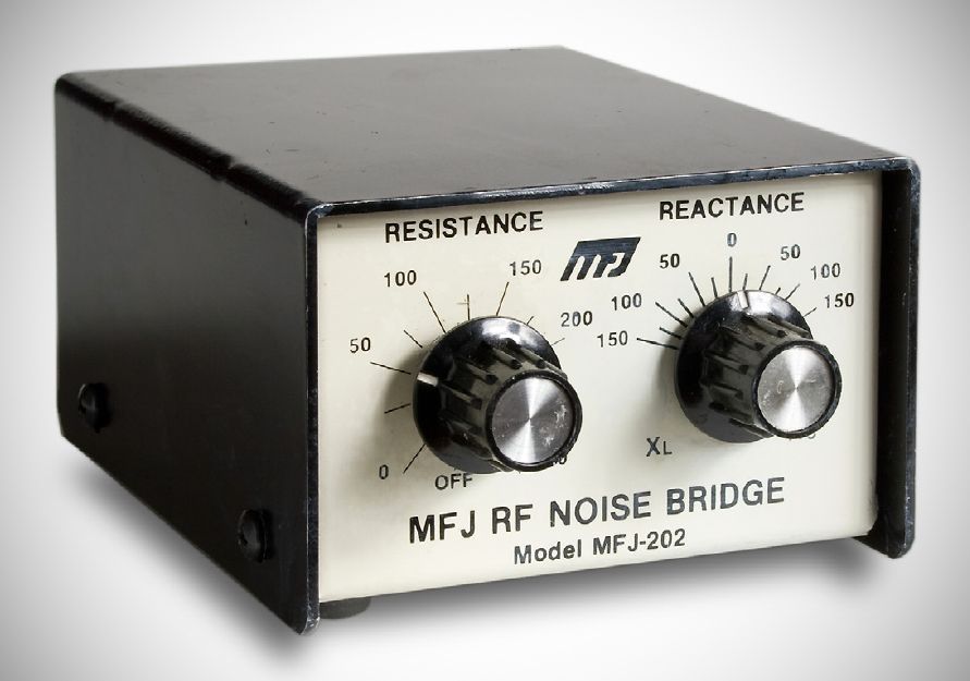
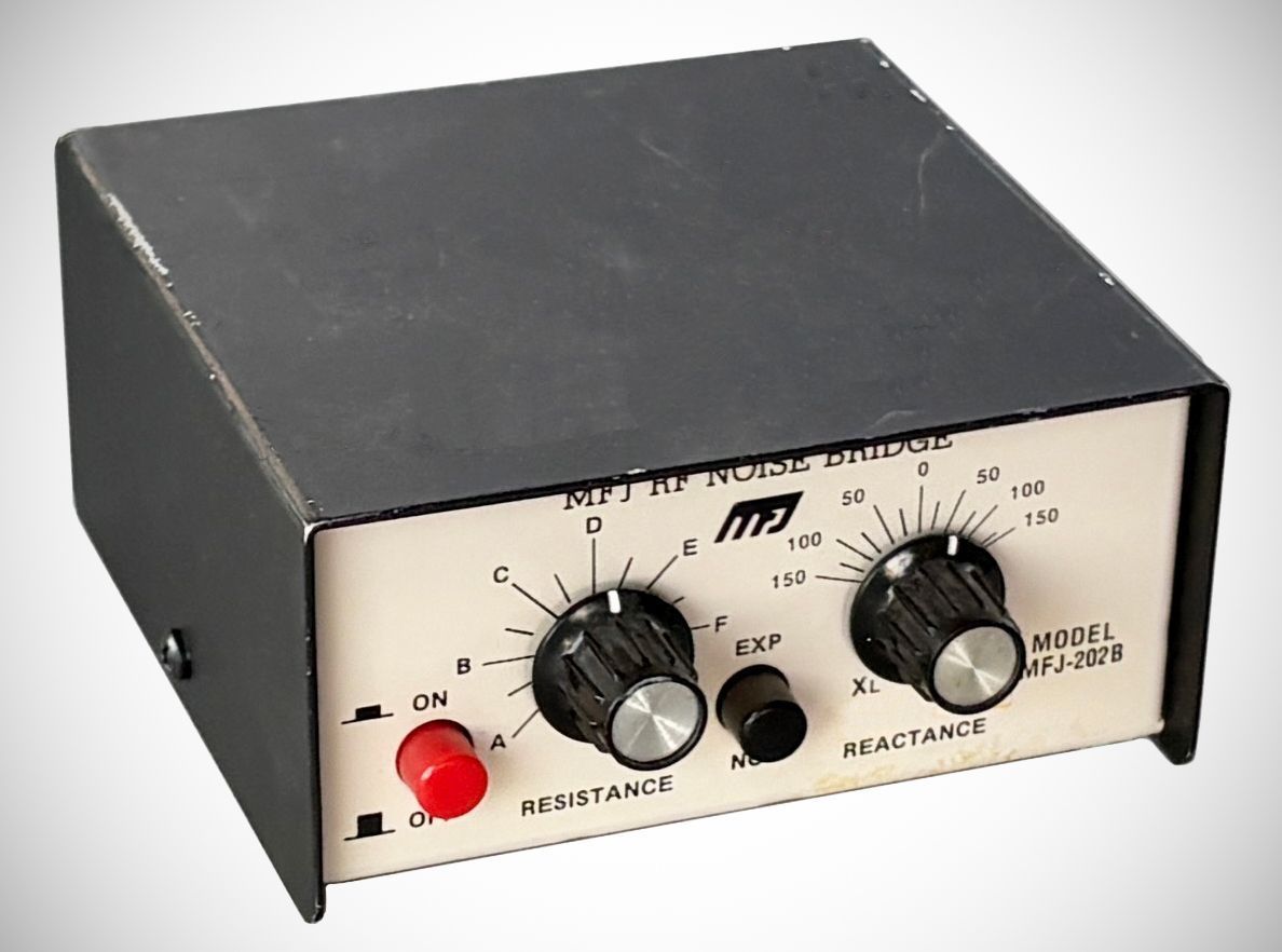
The MFJ-202(B) allows users to measure unknown antenna or circuit impedance by finding a "null" (minimum noise) on a receiver. It features two primary control dials: a Resistance (R) dial and a Reactance (X) dial. To improve accuracy, the Resistance dial uses a lettering system (A through G) that corresponds to a calibration chart located on the bottom of the unit. The device includes a built-in Range Expander to increase its measuring capacity for higher impedance values.
The primary difference between the MFJ-202 and the MFJ-202B is the addition of the Range Expander feature and upgraded internal components.
1. The Range Expander (Main Functional Difference)
The most significant upgrade in the MFJ-202B is the Range Expander switch.
MFJ-202: Limited to a standard resistance range (typically 0-250 ohms).
MFJ-202B: Features a built-in switch that inserts a 200-ohm resistor in parallel with the unknown impedance. This allows the unit to measure much higher impedances than the original model—up to 2000 ohms at 1 MHz and nearly 4000 ohms at higher frequencies (6–100 MHz).
2. Physical and Component Upgrades
Variable Capacitor: The original MFJ-202 often used a solid dielectric (poly) variable capacitor. The MFJ-202B was upgraded to an air-spaced variable capacitor, which is generally more stable and precise for RF measurements.
Resistance Scale: The MFJ-202B uses a "hand-calibrated" resistance scale marked with letters (A–G). This requires referring to a calibration chart on the bottom of the unit for precise ohm readings.
Offset Capacitor: The MFJ-202B utilizes an internal 180 pF offset capacitor to allow the Reactance (X) dial to sweep from inductive (XL) to capacitive (XC) through a center zero point.
Features
– Dual Measuring Capacity: Includes a standard mode and an "EXP" (Expander) mode for measuring impedances outside the normal range.
– Versatile Null Tuning: Measurements can be found by either adjusting the R and X dials at a set frequency or by setting the dials and varying the receiver frequency.
– Broad Application: Capable of measuring antenna resonant frequency, antenna impedance at any frequency, tuned circuit adjustment (series and parallel), and transmission line velocity factors.
– Battery Powered: Operates on a single 9-V battery with an integrated ON/OFF switch to conserve power.
– Transmatch Support: Can be used to tune a transmatch for an accurate transmitter match without radiating RF power.
Specifications
– Frequency Range: 1 MHz to 100 MHz
– Resistance Dial Range: 0 to 250 ohms
– Reactance Dial Range: –150 to +150 pF
– Unknown Resistance (Normal): 0 to 250 ohms at 1 MHz to 100 MHz
– Inductive Reactance (Normal): 0 to 500 ohms at 1 MHz; 0 to 5 ohms at 100 MHz
– Capacitive Reactance (Normal): 0 to 15 K ohms at 1 MHz; 0 to 150 ohms at 100 MHz
– Resistance Range (Expander): Up to 2000 ohms at 1 MHz; up to 3800 ohms at 6-100 MHz
– Reactance Range (Expander): Up to 360 ohms at 1 MHz; up to 1900 ohms at 6-100 MHz
– Connectors: "UNKNOWN" and "RECEIVER" (PL-259 coax recommended)
**Important Note:** To avoid permanent damage, never transmit through the Noise Bridge while it is connected to a transceiver.